The Logical Storage Manager (LSM) software is an integrated, host-based disk storage management software tool that enables you to configure disks to protect against data loss and improve disk use and performance. You can use the LSM software to perform disk management functions without disrupting users or applications accessing data on those disks.
This chapter introduces LSM features, capabilities, concepts, architecture,
and terminology.
The
volintro(8)
reference page also provides
LSM terms and commands.
1.1 Overview
In general, disk storage management often requires that for each file system or database that you:
Allocate and reallocate disk space as space requirements change
Address the space allocated for a particular file system or database
Access data through an application programming interface
These requirements are more easily accomplished by using the LSM software.
Table 1-1
compares these requirements for systems running
with and without the LSM software.
Table 1-1: Disk Storage Management With and Without the LSM Software
| Requirement | Without the LSM Software | With the LSM Software |
| Space Allocation | UNIX disks are divided into partitions. A partition is defined by its start address on the physical disk and its length. You must partition the disks according to the needs of the users on the system. You cannot move or extend in size a partition once it is in use. | The LSM software obtains space for a file system or raw database by creating an LSM volume of the appropriate size. An LSM volume is built from one or more areas of disk space (also called subdisks) located on one or more physical disks. This makes it possible to create LSM volumes by using disk space that is not contiguous with the space already in use, and to create LSM volumes that exceed the size of a physical disk. |
| Addressing | A UNIX partition is addressed through a physical address, generally referred to as the device name or devname. | LSM volumes are addressed using a
volume name.
You use a symbolic
disk media name
to refer to a disk that is managed by the LSM software(for example:
disk01).
This makes it easy to change an LSM volume and space allocation
when disks are moved, added, or removed in the configuration without affecting
applications. |
| Data Access | Data storage and retrieval on a UNIX partition is achieved through the standard block- and character-device interfaces using the physical device address. Because the partitioning of disks is not easily changed, it is difficult to ensure that data is placed on the available disk drives for optimal access and performance. | LSM volumes are accessed through the standard block- and character-device interfaces using volume names independent of the physical storage addresses used by the volume. Because you can change LSM volume configurations without interrupting user access to the data, you can dynamically change data placement for optimal access and performance. |
Table 1-2
summarizes features of the LSM software.
Table 1-2: LSM Features
| Feature | Description |
| Online storage management | Provides the ability to manage a system's disks as a pool of storage space for creating LSM volumes. By using LSM volumes instead of disk partitions, you can reconfigure LSM volumes to achieve the best performance and availability as your storage needs change without having to stop storage input and output (I/O), shut down the system, or back up and restore data. |
| Concatenation (disk spanning) | Combines multiple physical disks or portions of disks into a single, larger LSM volume for use by large file systems or databases. |
| Striping (RAID0) | Improves a system's disk I/O performance by interleaving the data within a volume across several physical disks. Also enables combining multiple physical disks into an LSM volume, similiar to concatentation, with better I/O performance. |
| Mirroring (RAID1) | Protects against data loss due to hardware malfunction by creating one or more mirror (duplicate) images of data on other disks. |
| Boot disk mirroring | Enables mirroring of critical system disk partitions used for booting and running the system to ensure that no single disk failure leaves the system unusable. |
| Dirty Region Logging (DRL) | Provides fast resynchronization of a mirrored volume after a system failure, by resynchronizing only the regions that were being updated when the system failed. DRL replaces the Block Change Logging (BCL) in previous LSM versions. |
| Striping and mirroring (RAID0+1) | Provides improved system performance and high data availability. |
| RAID5 | Provides higher data availability by storing parity information along with striped data, which improves read performance. |
| Hot-sparing | Automatically reacts to I/O failures on redundant (mirrored or RAID5) objects by relocating affected objects to spare disks or to other free disk space. |
| Encapsulation | Enables migration of existing data on disks and disk partitions to LSM volumes. |
| TruCluster support | Manages storage in a TruCluster environment the same way system storage space is managed. All LSM features are available within a TruCluster environment except for RAID5 and boot disk mirroring. |
LSM uses hierarchical objects to organize disk usage.
Table 1-3
identifies LSM objects and their purposes:
Table 1-3: LSM Objects
| Object | Purpose |
| Volume | A virtual disk device that appears as a disk partition to an application or file system |
| Plex | An instance of a volume's data |
| Subdisk | A logical representation of a set of contiguous disk blocks on a disk |
| Disk group | A collection of disks for use by LSM that share a common configuration |
| LSM disk | A contiguous area of disk space from which LSM allocates storage |
Each object has a dependent relationship on the next-lower object. LSM maintains a configuration database that describes the objects and their relationships.
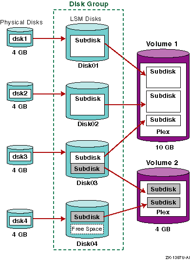
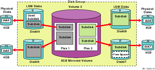
Figure 1-1 shows a simple LSM configuration consisting of two volumes built from four physical disks. The objects in the configuration are related as follows:
Physical disks are initialized for use by the LSM software and are assigned to a disk group where they become LSM disks.
At least one subdisk is mapped to each LSM disk. Each subdisk represents a set of contiguous disk blocks on a physical disk.
Subdisks are combined to form plexes. A plex is one copy or instance of the data.
Volumes are created from plexes, using either a single plex or multiple plexes. Volumes that contain multiple plexes are mirrored volumes. Each volume in Figure 1-1 has a single plex, so they are not mirrored.
Figure 1-1: LSM Objects and Their Relationships
The LSM software can use the following types of storage devices as supported by the operating system:
Standard Small Computer Systems Interface (SCSI)
Digital Storage Architecture (DSA)
Redundant arrays of independent disks (RAID) hardware devices are supported as standard disks, with each RAID device-logical unit viewed as one disk.
Generally, the entire disk is configured for use with the LSM software
rather than disk partitions, however, you can use disk partitions.
The LSM
software logically binds together the partitions from one or more physical
disks into a volume that represents the storage to applications and users
as a single virtual device.
Usually, disk partitions are accessed using a
device name ending in a letter from
a-h
(for example,
/dev/disk/dsk7b).
Figure 1-1
shows that four disks are used
with disk access names of
dsk1,
dsk2,
dsk3, and
dsk4.
1.3.2 LSM Disks
An LSM disk is created when you initialize a physical disk or disk partitions for use with the LSM software. Two regions are created on each LSM disk:
A usually small private region where the LSM software keeps its internal metadata such as disk header, configuration database, and so on.
A large public region used for storage
You must configure an LSM disk using one of three types of disk layout,
as shown in
Figure 1-2.
Figure 1-2: Types of LSM Disks
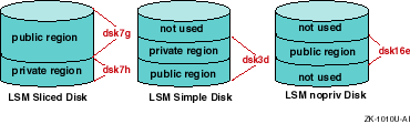
A
sliced disk
layout is used to configure
an entire disk for use with the LSM software.
This layout organizes the storage
into two regions on separate partitions -- a large public region (dsk7g) and a small private region (dsk7h).
This
is the most common and recommended layout.
A
simple disk
layout is used to configure
a single disk partition for use with the LSM software.
This layout organizes
the disk into public and private regions, but both regions are contained within
a single disk partition (dsk3d).
Whenever possible, configure the entire disk as a sliced disk instead of configuring individual disk partitions as simple disks. This ensures that the disk's storage is efficiently used and avoids using space for multiple private regions on the same disk.
A
nopriv disk
layout is used to configure
disk partitions for use with the LSM software that contain data that you want
to preserve, which is accomplished by a process called
encapsulation.
This type of layout has only a public region (dsk16e) and no private region.
A disk group is a named collection of LSM disks that share a common configuration database. The common configuration database contains records describing all the LSM objects in the disk group. The LSM software automatically maintains copies of the disk group's configuration database in the private region of one or more disks in the disk group in case of a disk failure.
When assigned to a disk group, the LSM disk acquires a
disk
media name, which provides a way of specifying the disk independently
of its location.
This name is either a name that you supply (for example,
payroll2), or a default name assigned automatically by the LSM software.
LSM volumes are created within a disk group and are restricted to the disks
within that group.
By default, LSM creates the
rootdg
disk group and,
unless otherwise specified, LSM operations are directed to this disk group.
You can create disk groups to simplify management and provide data availability.
For example:
On a system with many disks, you can divide disk usage into a few disk groups based on function. This reduces the size of the LSM configuration database for each disk group, and reduces the amount of overhead incurred in configuration changes.
If a system is unavailable for a prolonged amount of time, you can move the disks in a disk group to another system.
Automatic configuration provides a convenient way for you to view all the disks on the system to see which disks are currently configured for use with the LSM software and which are not.
When the LSM software starts, it obtains a list of known disk device
addresses from the operating system and checks the disk labels to locate all
its disk groups, configuration databases, and disks that were configured for
use with the LSM software.
Disks not initialized for use with the LSM software
are automatically configured into the
rootdg
disk group.
However the disk is not affected in any way.
Automatic configured disks are
displayed by utilities as a sliced disk with the status set to
unknown
because they are not currently configured for use with the LSM
software.
1.3.4 Subdisks
A subdisk is a set of contiguous blocks on an LSM disk that the LSM software uses to allocate disk space for use in volumes. Free space within an LSM disk's public region can be used to create a subdisk. Subdisks on the same disk cannot overlap each other.
An LSM disk may contain one or more subdisks, as shown in
Figure 1-1
where
disk01
and
disk02
each contain
a single large subdisk,
disk03
contains two subdisks, and
disk04
contains a single smaller subdisk.
1.3.5 Plexes
A plex is one or more subdisks that are organized into one of the following plex layout types:
A concatenated plex consists of one or more subdisks that create a contiguous address space. Data is allocated sequentially to the subdisks in the plex. This layout is often used for creating large volumes that span multiple disks.
A striped plex contains at least two subdisks, each on a different disk. Data is allocated alternately and evenly to the subdisks in the plex. This layout is useful for balancing the I/O load from applications across multiple disks.
A RAID5 plex consists of multiple subdisks on a multiple disks. Data and parity information are allocated alternately and evenly across the subdisks. This plex layout improves I/O performance for read operations, and provides data redundancy by using the parity information to reconstruct data after a disk failure.
A log plex is used with either a mirrored (RAID1) volume's data plexes or a RAID5 plex. A log plex consists of one subdisk that logs a mirrored volume's writes into a DRL or logs a RAID5 volume's writes into a RAID5 log. The recommended configuration is at least one log plex for each LSM mirrored (RAID1) or RAID5 volume.
The layout and number of plexes determines how the volume's data is
accessed from its underlying storage.
For example, a volume with two striped
plexes means that the data on a volumes is duplicated or mirrored, and both
copies are striped across multiple disks.
1.3.6 Volumes
An LSM volume is a virtual disk.
As with all UNIX disks, an LSM volume
has a block device interface and a character device interface.
A volume's
block device is located in the
/dev/vol/diskgroup_name/volume_name
directory.
A volume's
character device is in the
/dev/rvol/diskgroup_name/volume_name
directory.
Because these
interfaces support the standard UNIX
open,
close,
read,
write, and
ioctl
calls, an LSM volume can be used by file systems, databases,
and applications in the same manner as disk partitions.
For example,
Figure 1-3
shows how software that
previously used a disk partition can use an LSM volume.
Figure 1-3: Using LSM Volumes Like Other Disk Devices
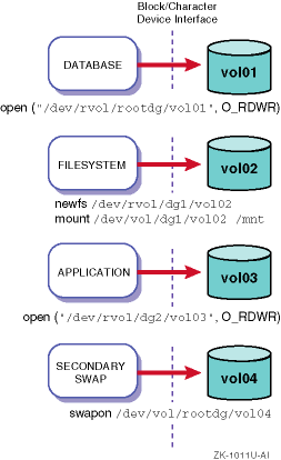
The storage space on the disk
is organized into four LSM volumes.
The
vol01
volume is
set up for database operations, the
vol02
volume contains
a file system that was created and mounted using the
newfs
and
mount
commands,
vol03
is used by
another application, and
vol04
is used for secondary swap.
An LSM volume can contain from one to 32 plexes, each containing one or more subdisks. Except for a log plex, each plex contains a copy of the volume's logical data address space.
You configure LSM volumes to have any of the following LSM volume layouts:
Simple (concatenated)
Striped (RAID0)
Mirrored (RAID1)
Striped and Mirrored (RAID0 plus RAID1)
RAID5
A simple volume is useful when there is insufficient contiguous space for a plex on any one disk.
Using an LSM simple volume has minimal I/O performance impact and allows greater flexibility compared to using a disk partition without LSM because you can make on line configuration changes, such as moving the data to a less busy disk, adding a mirror, and so on, without affecting users and applications.
A simple volume contains a single plex in which the data is mapped in a linear manner. You can build the plex from a single subdisk or multiple subdisks (concatenated volume), and the subdisks can reside on the same or different disks (spanned volume). Also, the subdisks do not have to be physically contiguous.
In a simple volume, data is accessed in the first subdisk from beginning to end, then data is accessed in the second subdisk from beginning to end, and so on until the end of the last subdisk.
Caution
Concatenating a plex across multiple disks increases the chance that a disk failure will result in the failure of its volume. Using mirroring or RAID5 (both described later) substantially reduces the chance that a single disk failure will result in a volume failure.
1.3.6.2 Striped Volumes (RAID0)
A striped volume is useful when writing large amounts of data, quickly reading data, or balancing I/O from multi-user applications across multiple disks.
Striping spreads data over two or more disks. A striped plex contains two or more subdisks, spread out over two or more disks. Data is interleaved evenly across the subdisks in a striped plex.
The subdisks are grouped into columns, with each disk limited to one column. Each column contains one or more subdisks. The number and sizes of subdisks per column can vary. You can add subdisks to columns as necessary.
Data is allocated in equal-sized units (called stripe units) that are interleaved between the columns. Each stripe unit is a set of contiguous blocks on a disk. The default stripe unit size is 64KB.
For example, if there are three columns in a striped plex and six stripe
units, data is striped over three physical disks, as shown in
Figure 1-4.
Figure 1-4: Example of a Striped Volume
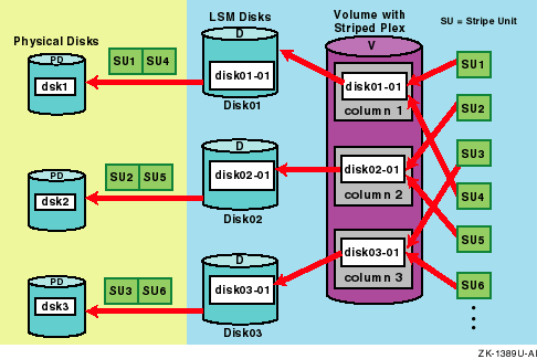
In Figure 1-4, the first and fourth stripe (SU1 and SU4) units are allocated in column 1; the second and fifth stripe units (SU2 and SU5) are allocated in column 2; and the third and sixth stripe units (SU3 and SU6) are allocated in column 3.
In Figure 1-4, there are two stripes. The first stripe is SU1 in column 1, SU2 in column 2, and SU3 3 in column 3. The second stripe is SU4 in column 1, SU5 in column 2, and SU6 in column 3.
Striping continues for the length of the columns (if all columns are the same length) or until the end of the shortest column is reached. Any space remaining at the end of subdisks in longer columns becomes unused space.
Caution
Striping a volume, or splitting a volume across multiple disks, increases the chance that a disk failure will result in failure of that volume. For example, if five volumes are striped across the same five disks, then failure of any one of the five disks requires that all five volumes be restored from backup. If each volume were on a separate disk, you only need to restore one volume. Using mirroring or RAID5 (both described later) substantially reduces the chance that a single disk failure causes any volumes to fail.
1.3.6.3 Mirrored Volumes (RAID1)
A mirrored volume is useful to reduce the chance that a single disk
failure results in volume failure.
A mirrored volume uses multiple mirrors
(plexes) to duplicate the information in a volume.
If a disk fails, the mirrored
volume on that disk becomes unavailable, but the system continues to operate
using the unaffected mirrored volume.
At least two plexes are required for
mirroring, as shown in
Figure 1-5.
Each plex must
contain disk space from different disks for the redundancy to be effective.
Figure 1-5: Example of a Mirrored Volume
When striping or spanning across a large number of disks, failure of
any one of those disks will generally make the entire plex unusable.
The chance
of one out of several disks failing makes it worthwhile to consider mirroring
to improve the reliability and availability of a striped or spanned volume.
1.3.6.3.1 Dirty-Region Logging
Dirty-region logging (DRL) is an option that provides a fast recovery of mirrored volumes after a system failure. DRL logically divides a mirrored volume into a set of consecutive regions and marks regions that change due to I/O writes to the volume as dirty. When the system restarts after a failure, only those regions of the volume that are marked as dirty in the DRL are recovered.
A write operation to a volume marks a region dirty in the log before the data is written. The dirty bit for a region is not cleared immediately after writing the data to the region. Instead, it remains marked as dirty until the corresponding volume region becomes the least recently used. If a bit for a given region is marked dirty and another write to the same region occurs, the log does not need to be written to before the write operation occurs, thus reducing write overhead operations associated with using a DRL.
LSM maintains a limited number of dirty bits as still dirty even after the I/O was completed on all the volume's plexes. This balances the benefits of not having to log subsequent writes to the same region against how many regions are subsequently recovered if the system fails.
If you do not use DRL and the system fails, the LSM software must copy
the full contents of a volume between its mirrors to restore and resynchronize
all plexes.
Although this process occurs in the background and the volume
is still available, it can be a lengthy I/O-intensive procedure and may result
in many areas of the volume being unnecessarily recovered.
1.3.6.3.2 Migrating From Block Change Logging to DRL
The DRL feature is a replacement for block change logging (BCL). When you import a disk group from a previous LSM version, either automatically during an upgrade installation or manually, existing mirrored volumes with BCL enabled are automatically reconfigured to DRL if the BCL log subdisk is at least 2 blocks. If the BCL log subdisk is less than 2 blocks, the volume is usable, but logging is disabled after the import.
A DRL must be configured with two or more sectors, preferably an even number because the last sector in a log with an odd number of sectors is not used. The log size is normally proportional to the volume size. If a volume is less than 2 GB, a log of two sectors is sufficient. The log subdisk size should then increase by two sectors for every additional 2 GB of volume size.
It is recommended that you use of the default log length provided by
the
volassist
command.
If the BCL cannot be migrated to DRL, logging is disabled on that volume. Logging can be reenabled by removing the invalid logs and enabling DRL appropriately. See Section 5.3.3.3 for information on enabling DRL logging.
Note
A DRL log subdisk must be at least 65 blocks when using LSM in a TruCluster environment.
See the
vollogcnvt(8)
reference page for more information on migrating BCL to DRL.
1.3.6.4 Striped and Mirrored Volumes (RAID0 and RAID1)
A striped and mirrored volume spreads data across multiple disks while
providing redundancy of data.
Configuring a LSM volume to be both mirrored
and striped is a common and effective way to improve both performance and
availability for a volume.
You create a striped and mirrored volume by configuring
each of the volume's data plexes, or mirrors, to have a stripe layout.
You
must allocate the striped plex and its mirror on separate disks for striping
and mirroring to be effective.
1.3.6.5 RAID5 Volumes
Although both mirroring (RAID1) and RAID5 provide redundancy of data, the approaches differ. Mirroring provides data redundancy by maintaining multiple copies of a volume's data. Data written to a mirrored volume is duplicated in all copies. If a portion of a mirrored volume fails, the system continues to use the other copies of the data.
RAID5 provides data redundancy through the use of parity. While data is written to a RAID5 volume, a parity value is also calculated by performing an exclusive OR (XOR) procedure on data. The resulting parity is written to the volume. If a portion of a RAID5 volume fails, the data that was on that portion of the failed volume is recreated from the remaining data and the parity.
Note
Mirroring of RAID5 volumes is not currently supported.
A RAID5 volume in a TruCluster environment is not currently supported.
1.3.6.5.1 Left-Symmetric Layout
There are several layouts for data and parity that can be used for a RAID5 volume. The layout selected for the LSM implementation of a RAID5 volume is the left-symmetric layout. The left-symmetric layout provides optimal performance for both random I/O and large sequential I/O.
The left-symmetric layout stripes both data and parity across columns, placing the parity in a different column for every stripe of data. The first parity stripe unit is located in the right column of the first stripe. Each successive parity stripe unit is located in the next stripe, left-shifted one column from the previous parity stripe unit location. If there are more stripes than columns, the parity stripe unit placement begins in the right column again. Data is organized starting to the right of the parity stripe unit.
Figure 1-6
illustrates a left-symmetric parity
layout consisting of five disks (one per column).
Figure 1-6: Left-Symmetric Layout
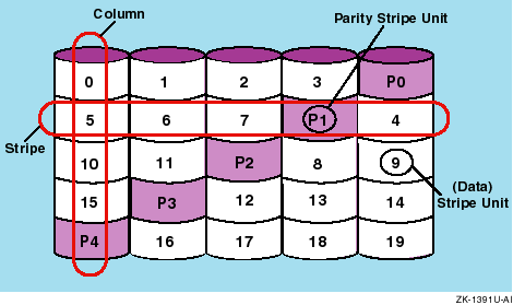
In Figure 1-6, data organization for the first stripe begins at P0 and continues to stripe units 0 through 3. Data organization for the second stripe begins at P1, then continues to stripe unit 4, and on to stripe units 5 through 7. Data organization proceeds in this manner for the remaining stripes.
Each parity stripe unit contains the result of an exclusive OR (XOR) procedure performed on the data in the data stripe units within the same stripe. If data on a disk corresponding to one column is inaccessible due to hardware or software failure, data is restored by performing an XOR procedure on the contents of the remaining columns' data stripe units against their respective parity stripe units (for each stripe).
For example, if the disk corresponding to the leftmost column in Figure 1-6 fails, then the volume is placed in a degraded mode. While in degraded mode, the data from the failed column is re-created by performing the XOR procedure on stripe units 1 through 3 against parity stripe unit P0 to recreate stripe unit 0, then performing the XOR procedure on stripe units 4, 6, and 7 against parity stripe unit P1 to re-create stripe unit 5, and so on.
Note
Failure of multiple columns in a plex with a RAID5 layout detaches the volume. This means that the volume cannot satisfy read or write requests. Once the failed columns are recovered, you might have to recover the user data from backups.
If a disk and the system fail, it is possible for data not involved in active writes to be lost or corrupt. If this double failure occurs, it is unknown if the data or parity were actually written. Therefore, the recovery of the corrupted disk may be corrupted itself.
You can use RAID5 logging to prevent corruption of recovery data. A RAID5 log of the new data and parity is made on a persistent device, such as a disk device or nonvolatile RAM. The new data and parity are written to the disks.
You can associate a log with a RAID5 volume by attaching it as additional, non-RAID5 layout plexes. More than one log plex can exist per RAID5 volume, in which case the RAID5 logs are mirrored.
Note
The recommended procedure it to always use a log with RAID5 volumes. By default,
volassistcreates a log when you create a RAID5 volume.
There are two methods to administering LSM objects:
The top-down approach, where you use commands that automatically configure and create relationships between the LSM objects.
The bottom-up approach, where you use commands to manually configure and create relationships between the LSM objects.
The top-down approach is the recommended method for most users because
it allows the LSM software to manage the free disk space and control the relationship
of LSM objects.
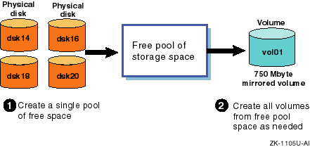
As shown in
Figure 1-7, the top-down approach
involves a two-step process.
First, LSM disks are placed into a disk group
and managed as a single, large pool of free storage space.
Then, as storage
space is needed, you request disk space and LSM allocates the space from this
free pool.
Based on your specifications (for example, striped and mirrored
volumes), the LSM software automatically allocates the storage from different
LSM disks to satisfy the volume configuration requirements.
Figure 1-7: Top-Down Storage Allocation with the LSM software
The bottom-up approach is the recommended method for advanced users who want to manage the free disk space themselves, or who need more control over the relationship of LSM objects. This approach requires detailed knowledge of LSM technology and commands -- especially when creating a mirrored, striped, or RAID5 volume in which the volume's subdisks are defined and configured on different disks.
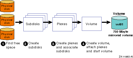
As shown in
Figure 1-8, the bottom-up approach requires
considerably more user interaction and detailed knowledge of the LSM software,
because you must explicitly perform each of the actions that are done automatically
with the top-down approach -- that is, find free space, create subdisks,
create and associate plexes, create the volume, attach plexes, and start the
volume.
Figure 1-8: Bottom-Up Storage Allocation with the LSM software
1.4.3 LSM Administrative Commands and Interfaces
You administer LSM objects using:
A set of commands ranging from common commands (top-down) that require minimal user input to advanced commands (bottom-up) that require numerous parameter and option values. You must log on as root to use LSM commands.
A menu-based, interactive interface called
voldiskadm.
This interface provides default values and online help.
A java-based graphical user interface (GUI) called Storage Administrator. The Storage Administrator allows you to manage local or remote systems on which LSM is running.
A bit-mapped GUI called Visual Administrator. The Visual Administrator allows you to view and manage disks and volumes, and perform limited file system administration. This GUI requires a bit-mapped display, the Basic X Environment software subset, and the LSM software license.
You can use the LSM interfaces interchangeably.
That is, objects created
by one interface are compatible with objects created by other LSM interfaces.
1.4.3.1 LSM Commands
LSM commands are divided into two main categories:
Common commands that support the top-down approach for storage space management and common operations.
Advanced commands that support the bottom-up approach for storage space management and specialized operations.
Table 1-4 lists the common LSM commands and their functions.
Table 1-4: Common LSM Commands
| Command | Function |
| volsetup | Initialize LSM and rootdg (used once after a new installation) |
| voldiskadd | Interactively add a disk or list of disks for use with LSM |
| voldiskadm | Run the interactive menu interface to do common disk-related operations |
| voldisksetup | Add a disk or a list of disks for use with LSM (with -i option) |
| voldisk | Display LSM disk information (and other functions) |
| voldg | Display disk groups (and other functions) |
| volassist | Create, mirror, back up, and move volumes |
| volprint | Display LSM configuration information |
| volmirror | Mirror volumes on a disk |
| volrestore | Backup or restore the LSM configuration database |
| volwatch | Monitor LSM for failure events and perform hot sparing |
| volevac | Evacuate all volumes from a disk |
| volrecover | Resynchronize plexes after a crash or disk failure |
| volencap | Create a script to encapsulate partitions that contain existing data |
| volreconfig | Run a script to perform encapsulation |
| volrootmir | Mirror the root and swap volumes |
| lsmsa | Start the Storage Administrator GUI |
Table 1-5
lists the advanced LSM commands
and their functions.
Table 1-5: Advanced LSM Commands
| Command | Function |
| volinstall | Customize the LSM environment |
| voldisk | Manage LSM disks |
| voldg | Manage LSM disk groups |
| volmake | Create LSM objects (volume, plex, subdisk) |
| volsd | Perform LSM operations on subdisks |
| volplex | Perform LSM operations on plexes |
| volume | Perform LSM operations on volumes |
| voledit | Create, modify, and remove LSM records |
| volstat | Display LSM statistics |
| voldctl | Control daemon operations |
| volmend | Mend simple problems in configuration records |
| volnotify | Display LSM configuration events |
| voltrace | Trace I/O operations on volumes |
For more information on a command, see the reference page corresponding
to its name.
For example, for more information on the
volassist
command, enter:
#
man volassist
1.4.3.2 The
voldiskadm Menu Interface
The
voldiskadm
menu interface allows you to perform
basic disk and volume procedures.
You start the
voldiskadm
menu interface by entering
the following command:
#
voldiskadm
Example 1-1
shows the
voldiskadm
main menu.
To perform a procedure, choose an operation from the
main menu and the
voldiskadm
command prompts you for information.
The
voldiskadm
command provides default values when possible.
You can press Return to use the default value or enter a new value.
Enter
?
at any time to view online help.
Example 1-1: Main Menu for the LSM voldiskadm Interface
Logical Storage Manager Support Operations
Menu: VolumeManager/Disk

 1      Add or initialize one or more disks
 2      Encapsulate one or more disks
 3      Remove a disk
 4      Remove a disk for replacement
 5      Replace a failed or removed disk
 6      Mirror volumes on a disk
 7      Move volumes from a disk
 8      Enable access to (import) a disk group
 9      Remove access to (deport) a disk group
 10     Enable (online) a disk device
 11     Disable (offline) a disk device
 12     Mark a disk as a spare for a disk group
 13     Turn off the spare flag on a disk
 14     Recover plexes and volumes after disk replacement
 list   List disk information

 ?      Display help about menu
 ??     Display help about the menuing system
 q      Exit from menus

Select an operation to perform:
See the
Appendix D
and the
voldiskadm(8)
reference
page for more information on
voldiskadm
interface.
1.4.3.3 The Storage Administrator
The Storage Administrator is a java-based GUI that displays a hierarchical view of LSM objects and their relationships.
You use the Storage Administrator to view and manage LSM objects on a local or remote (client) system. The Storage Administrator consists of a server (daemon) and a client. The server daemon runs on a system on which LSM is initialized and running. The client runs on a system that supports the Java run time environment.
The Storage Administrator provides dialog boxes in which you enter information to create or manage LSM objects. Completing a dialog box may be the equivalent of entering several commands.
See
Chapter 9
for more information on the Storage
Administrator.
1.4.3.4 The Visual Administrator
The Visual Administrator is a GUI that you can use to manage LSM disks, volumes, and some basic file-system objects. The Visual Administrator displays windows in which LSM objects are represented as icons. You use menus and mouse point-and-click and drag-and-drop techniques to select and manage LSM objects. The Visual Administrator uses LSM commands to carry out operations.
See
Appendix B
for more information on the
Visual Administrator.
1.5 LSM Architecture and Components
The LSM device driver is between the file systems and the disk device drivers. An LSM-built kernel includes volume device drivers that provide a level of abstraction between the disks and the file systems or third-party databases. The file systems and databases are placed on LSM volumes and perform I/O requests to an LSM volume in the same way that they perform I/O requests to any other disk driver.
Once an LSM volume is defined and configured, the file systems and databases issue I/O requests directly to the LSM volume, not to the device drivers.
Figure 1-9
shows the relationships between applications,
the kernel, file systems, device drivers, and the LSM configuration databases.
Figure 1-9: LSM Architecture
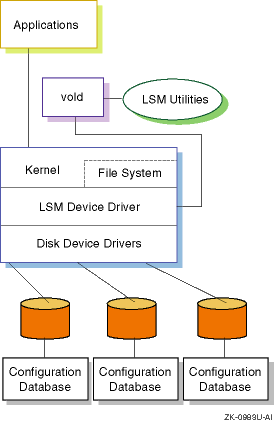
Table 1-6
describes LSM components and their functions.
Table 1-6: LSM Components
| Component | Function |
Volume configuration daemon (vold) |
A daemon that: - Provides the interface between the LSM software and the kernel- Takes requests for configuration changes from other utilities, makes the changes, and communicates them to the kernel- Initializes the LSM software when the system boots |
Volume device driver (volconfig) |
An interface that LSM drivers use for loading or changing the kernel's LSM configuration. |
Volume extended I/O daemons (voliod) |
Internal kernel threads that the LSM driver uses for LSM error handling and recovery, and additional I/O threads to improve performance when writing to a mirror or a DRL. |
/etc/vol/volboot
file |
A configuration file that the LSM software uses when it starts to locate the LSM configuration databases. |
| Configuration database | A database that contains records describing all the LSM objects and layouts (volumes, plexes, subdisks, disk media names, and disk access names) in a disk group. Typically, the LSM software maintains multiple copies of the configuration database in a disk group in case of a disk failure. |