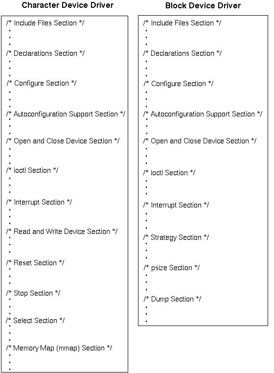
The sections that make up a Digital UNIX device driver differ depending on whether the driver is a block, character, or network driver. Figure 5-1 shows the sections that a character device driver can contain and the possible sections for a block device driver. Device drivers are not required to use all of the sections and more complex drivers can have additional sections.
Both types of drivers contain:
The configure section contains the code that implements the configure interface. Chapter 6 explains how to implement a configure interface.
The autoconfiguration support section contains the code that implements the probe, attach, unattach, and slave interfaces. Section 7.1, Section 7.2, and Section 7.3 explain how to implement the probe, attach, and unattach interfaces, respectively. Section 7.4 explains how to set up the slave interface.
The open and close device section contains the code that implements the open and close interfaces. Section 10.1 and Section 10.2 explain how to implement the open and close interfaces, respectively.
The ioctl section contains the code that implements the ioctl interface. Section 10.3 explains how to implement an ioctl interface.
The interrupt section contains the code that implements the device driver's interrupt handler. Section 7.1.7 shows how to implement an interrupt handler for a driver that uses shared interrupts. Section 10.4 explains how to set up an interrupt handler.
The block device driver can also contain:
The strategy section contains the code that implements the device driver's strategy interface. Section 9.3 explains how to set up a strategy interface.
The psize section contains the code that implements the device driver's psize interface. Section 9.2 explains how to set up a psize interface.
The dump section contains the code that implements the device driver's dump interface. Section 9.1 explains how to set up a dump interface.
The character device driver contains the following sections not contained in a block device driver:
The read and write device section contains the code that implements the read and write interfaces. Section 8.1 and Section 8.2 explain how to implement the read and write interfaces, respectively.
The reset section contains the code that implements the device driver's reset interface. Section 8.3 explains how to set up a reset interface.
The stop section contains the code that implements the device driver's stop interface. Section 8.5 explains how to set up a stop interface.
The select section contains the code that implements the device driver's select interface. Section 8.4 explains how to implement a select interface.
The memory map section contains the code that implements the device driver's mmap interface. Section 8.6 explains how to set up an mmap interface.
The include files section and the declarations section are described in the following sections. There are two data structures that you must initialize in the declarations section: driver and dsent (for block and character drivers). The following sections also describe the members of these structures.
Data structures and constant values are defined in header files that you include in the include files section of the driver source code. The number and types of header files you specify in the include files section vary, depending on such things as what structures, constants, and kernel interfaces your device driver references. You need to be familiar with:
The following sections describe these categories of header files. Section 5.1.2 shows a device register header file, using the /dev/none driver as an example. Section 5.1.4 shows an include files section, using the /dev/none driver as an example. Writing Device Drivers: Reference provides reference page descriptions of the header files that Digital UNIX device drivers use most frequently.
The following example lists the header files that device drivers use most frequently:
#include <sys/types.h>
#include <sys/errno.h>
#include <io/common/devdriver.h>
#include <sys/uio.h>
#include <machine/cpu.h>
#include <sys/conf.h>
#include <sys/sysconfig.h>
The example shows that device drivers should not use explicit pathnames. Using angle brackets (< and >) means you will not have to make changes to your device driver if the file path changes.
The following sections contain brief descriptions of the previously listed common driver header files.
The header file /usr/sys/include/sys/types.h defines system data types used to declare members in the data structures referenced by device drivers. Table 5-1 lists the system data types defined in this file that device drivers use most frequently.
| Data Type | Meaning |
| daddr_t | Block device address |
| caddr_t | Main memory virtual address |
| ino_t | Inode index |
| dev_t | Device major and minor numbers |
| off_t | File offset |
| paddr_t | Main memory physical address |
| time_t | System time |
| u_short | unsigned short |
The /usr/sys/include/sys/types.h header file includes the file /mach/machine/vm_types.h. This file defines the data type vm_offset_t, which driver writers should use when addresses are treated as arithmetic quantities (that is, as ints and longs). The vm_offset_t data type is defined as unsigned long on Alpha systems.
The header file /usr/sys/include/sys/errno.h defines the error codes returned to a user process by a device driver. Examples of these error codes include EINVAL (invalid argument), ENODEV (no such device), and EIO (I/O error).
The header file /usr/sys/include/io/common/devdriver.h defines structures, constants, data types, and external interfaces that device drivers and the autoconfiguration software use. Two opaque data types that you can use to make your device drivers more portable are io_handle_t and dma_handle_t.
Section 7.1.2 and Section 18.6.1 discuss the I/O and DMA handles.
The header file /usr/sys/include/sys/uio.h contains the definition of the uio structure. The kernel sets up and uses the uio structures to read and write data. Character device drivers include this file because they may reference the uio structure.
Section 8.1.2 discusses the uio structure.
The cpu.h file defines a variety of structures and constants related to the CPU. You include the cpu.h file in block and character device drivers when calling any of the spl interfaces. The reason for this is that the spl interfaces map to an assembler interface.
The header file /usr/sys/include/sys/conf.h defines the dsent structure (for block and character devices). You should include the conf.h file in block and character device drivers because these drivers declare an instance of and set the associated members of the dsent structure. For statically and dynamically configured device drivers, the driver writer declares and initalizes an instance of a dsent structure and then passes the address of this initialized structure to the devsw_add interface. This interface adds the I/O services interfaces (and other information) for block and character drivers to the device switch table and reserves an associated major number.
Section 5.4 describes the device switch table.
The header file /usr/sys/include/sys/sysconfig.h defines operation codes and data structures used by the device driver's configure interface. The operation codes define the action to be performed by the device driver's configure interface. Examples of the operation types include configure, unconfigure, and query. This file also defines many of the constants that are shared between the cfgmgr framework and the drivers themselves. Within this file also appears the definition of the cfg_attr_t data structure that is passed to the driver's configure interface and the definition of the cfg_subsys_attr_t data structure that device drivers initialize.
Section 6.5 shows how to set up the configure interface.
The device register header file contains any public declarations that the device driver uses. This file usually contains the device register offset definitions associated with the device. A device register offset is a C #define that maps to the register of some device. These registers are often referred to as the device's control status register (or CSR) addresses. The device driver writer creates the device register header file.
The following example shows the device register offest definitions contained in a device register header file for a device driver that uses the CSR I/O access kernel interfaces to access a device's CSR addresses. Note that these constants map to the device registers.
/***************************************************
 * Define offsets to nvram device registers        *
 ***************************************************/
#define ENVRAM_CSR      0xc00  /* CSR */
#define ENVRAM_BAT      0xc04  /* Battery Disconnect */
#define ENVRAM_HIBASE   0xc08  /* Ext. Mem Config */
#define ENVRAM_CONFIG   0xc0c  /* EISA config reg */
#define ENVRAM_ID       0xc80  /* EISA ID reg */
#define ENVRAM_CTRL     0xc84  /* EISA control */
#define ENVRAM_DMA0     0xc88  /* DMA addr reg 0 */
#define ENVRAM_DMA1     0xc8c  /* DMA addr reg 1 */
Section 7.1.9 shows how the /dev/none driver uses the CSR I/O access kernel interfaces read_io_port and write_io_port to read from and write to the device's CSR addresses. See Section 7.1.10 to learn how to build your own macros based on the read and write macros that Digital provides.
The device register header file for the /dev/none driver is called nonereg.h. It contains public declarations and the device register offset for the NONE device. Device drivers implemented to operate with real devices need to declare more register offsets and more public declarations.
#define DN_GETCOUNT   _IOR(0,1,int) [1]
#define DN_CLRCOUNT   _IO(0,2)      [2]


#define NONE_CSR 0 [3]
The NONE_CSR offset is a 64-bit read/write CSR/LED register. [Return to example]
Each bus implemented on Alpha processors and Digital UNIX has a specific header file. The bus-specific header files contain #define statements, data structure definitions, and other information associated with a specific bus. To write portable device drivers across multiple bus architectures, you need to consider how to include bus-specific header files in the include files section of your device driver.
The following list describes some of the bus-specific header files:
Contains definitions for EISA/ISA bus support
Contains definitions for PCI bus support
Contains definitions for TURBOchannel bus support
You include the header file for the bus that your driver operates on. For example, if your device driver controls a device that connects to a controller that operates on an EISA and PCI bus, you include the files eisa.h and pci.h. The following example shows how to include the bus-specific header files for the EISA, ISA, PCI, and TURBOchannel buses:
.
.
.

#include <io/dec/eisa/eisa.h> /* EISA/ISA bus */
#include <io/dec/pci/pci.h>   /* PCI bus */
#include <io/dec/tc/tc.h>     /* TURBOchannel bus */

.
.
.
The following example shows the include files section for the /dev/none device driver:
#include <sys/param.h>
#include <sys/systm.h>
#include <sys/ioctl.h>
#include <sys/tty.h>
#include <sys/user.h>
#include <sys/proc.h>
#include <sys/map.h>
#include <sys/buf.h>
#include <sys/vm.h>
#include <sys/file.h>
#include <sys/uio.h>
#include <sys/types.h>
#include <sys/errno.h>
#include <sys/conf.h>
#include <sys/kernel.h>
#include <sys/devio.h>
#include <hal/cpuconf.h>
#include <sys/exec.h>
#include <io/common/devdriver.h>
#include <sys/sysconfig.h>
#include <kern/kalloc.h>

#include <io/dec/tc/tc.h> [1]

#include <machine/cpu.h>
#include <io/ESA100/nonereg.h> [2]


#define NO_DEV -1 [3]
#define MAJOR_INSTANCE 1

#define MAX_NNONE 8 [4]
#include <io/dec/eisa/eisa.h>
#include <io/dec/eisa/isa.h>
#include <io/dec/pci/pci.h> [Return to example]
The previous lines include the common header files.
Writing Device Drivers: Reference provides reference page descriptions of the header files that Digital UNIX device drivers use most frequently. [Return to example]
Note that MAX_NNONE is used in the none_attributes table, specifically as the maximum value for the numunit attribute field. Section 6.3 shows the declaration and initialization of the none_attributes table. This example uses the static allocation model technique described in Section 2.6.1. [Return to example]
The declarations section of a block or character device driver contains:
Device drivers must initialize a driver structure and a dsent structure for block and character device drivers. Device drivers also typically declare an array of pointers to controller structures. The following example shows a typical declarations section, using the /dev/none driver as an example. Following the example are sections that describe in more detail the driver and dsent structures. Chapter 17 describes the controller structure.
The following example shows the declarations section for the /dev/none device driver:
#define DN_RESET 0001 [1]
#define DN_ERROR 0002 [2]


#define DN_OPEN  1 [3]
#define DN_CLOSE 0 [4]


int noneprobe(), nonecattach(), noneintr();
int noneopen(),  noneclose(),   noneread(), nonewrite();
int noneioctl(), none_ctlr_unattach(); [5]


struct controller *noneinfo[MAX_NNONE]; [6]


struct driver nonedriver = {
        noneprobe,
        0,
        nonecattach,
        0,
        0,
        0,
        0,
        0,
        "none",
        noneinfo,
        0,
        0,
        0,
        0,
        0,
        none_ctlr_unattach,
        0
}; [7]


struct none_softc {
	int sc_openf;
	int sc_count;
	int sc_state;
} none_softc[MAX_NNONE]; [8]

int none_config = FALSE;  [9]
int none_devno = NO_DEV; [10]
int NNONE = 1; [11]

ihandler_id_t *none_id_t[MAX_NNONE]; [12]


int none_is_dynamic = 0; [13]

int num_none = 0;   [14]

int callback_return_status = ESUCCESS; [15]

extern int nodev(), nulldev(); [16]


struct dsent none_devsw_entry = {
        noneopen,
        noneclose,
        nodev,
        noneread,
        nonewrite,
        noneioctl,
        nodev,
        nodev,           /* d_psize */
        nodev,
        nodev,
        nodev,
        0,
        0,
        NULL,
        DEV_FUNNEL,
        0,
        0,
}; [17]
The MAX_NNONE constant is used to represent the maximum number of NONE controllers. This number is used to size the array of pointers to controller structures. [Return to example]
The value zero (0) indicates that the /dev/none driver does not make use of a specific member of the driver structure. The following list describes those members initialized to a nonzero value by the example driver:
Section 7.1 shows how to implement noneprobe.
The NONE device does not need an attach interface because it does not deal with any real hardware. However, Section 7.2.1 provides a nonecattach interface stub for future expansion.
You index this array with the controller number as specified in the ctlr_num member of the controller structure. Section 17.2.4 describes the ctlr_num member.
The none_ctlr_unattach interface removes the controller structure associated with specific NONE devices from the list of controller structures that it handles. Section 7.2.1 shows how to implement none_ctlr_unattach.
Stores a constant value that indicates that the NONE device is open. This member is set by the noneopen and noneclose interfaces discussed in Section 10.1.2 and Section 10.2.2, respectively.
Stores the count of characters. This member is set by the nonewrite and noneioctl interfaces discussed in Section 8.2.2 and Section 10.3, respectively.
Stores a constant value that indicates the state the driver is in. This member is not currently used.
Section 6.3 shows the declaration and initialization of the none_attributes table. [Return to example]
Section 7.1.8 shows how noneprobe uses none_is_dynamic. Section 7.3.3 shows how none_ctlr_unattach uses none_is_dynamic. Section 6.6.3 and Section 6.7 show how none_configure uses none_is_dynamic. [Return to example]
Section 10.1 shows how to implement noneopen.
Section 10.2 shows how to implement noneclose.
Section 8.1 shows how to implement noneread.
Section 8.2
shows how to implement
nonewrite.
Section 10.3 shows how to implement noneioctl.
This constant signifies that the operating system schedules a device driver onto a single processor configuration (that is, the /dev/none device driver is not SMP safe).
The driver structure defines driver entry points and other driver-specific information. You declare and initialize an instance of this structure in the declarations section of the device driver. The bus configuration code uses the entry points defined in this structure during device autoconfiguration. The bus configuration code fills in the dev_list and ctlr_list arrays. The driver interfaces use these arrays (members of the device and controller structures) to get the structures for specific devices or controllers.
Driver writers need to be intimately familiar with the members of the driver structure. The following code shows the C definition:
struct driver {
  int     (*probe)();
  int     (*slave)();
  int     (*cattach)();
  int     (*dattach)();
  int     (*go)();
  caddr_t *addr_list;
  char    *dev_name;
  struct  device **dev_list;
  char    *ctlr_name;
  struct  controller **ctlr_list;
  short   xclu;
  int     addr1_size;
  int     addr1_atype;
  int     addr2_size;
  int     addr2_atype;
  int     (*ctlr_unattach)();
  int     (*dev_unattach)();
};
The following sections discuss all of these members. Writing Device Drivers: Reference provides a reference page description of this data structure.
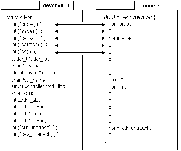
The probe member specifies a pointer to the driver's probe interface, which is called to verify that the controller exists. The slave member specifies a pointer to the driver's slave interface, which is called once for each device connected to the controller.
The cattach member specifies a pointer to the driver's controller attach interface, which is called to allow controller-specific initialization. You can set this pointer to NULL. The dattach member specifies a pointer to the driver's device attach interface, which is called once for each slave call that returns success. You use the device attach interface for device-specific initialization. You can set this pointer to NULL.
The go member specifies a pointer to the driver's go interface, which is not currently used. Figure 5-2 shows that the driver writer initializes these members to the values contained in the nonedriver structure discussed in Section 5.2. This data structure appears in none.c, the source file for the /dev/none device driver.
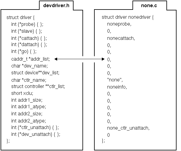
The addr_list member specifies a list of optional CSR addresses. Figure 5-3 shows that the driver writer initializes this member to the value zero (0) because this entry is not used for device drivers that operate on the TURBOchannel bus.
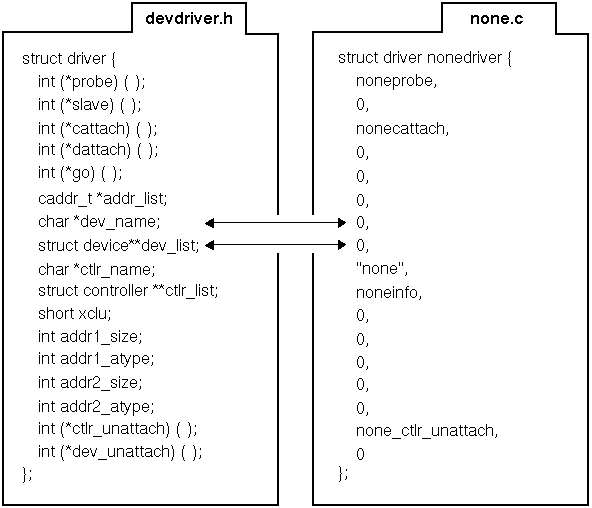
The dev_name member specifies the name of the device connected to this controller. The dev_list member specifies an array of pointers to device structures currently connected to this controller. This member is indexed through the logunit member of the device structure associated with this device. Section 17.3 describes the device structure. Figure 5-4 shows that the driver writer initializes these members to the value zero (0), which indicates that there is no device connected to the controller and that there is no array of pointers to device structures.
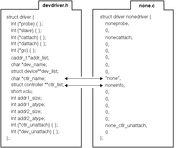
The ctlr_name member specifies the controller name. The ctlr_list member specifies an array of pointers to controller structures. The system uses this member when multiple controllers are controlled by a single device driver. This member is indexed through the ctlr_num member of the controller structure associated with this device. Section 17.2 describes the controller structure. Figure 5-5 shows that the driver writer initializes these members to the values none and noneinfo.
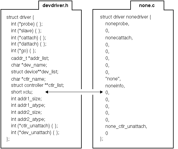
The xclu member specifies a field that is not currently used. Figure 5-6 shows that the driver writer initializes this member to the value zero (0).
The addr1_size member specifies the size (in bytes) of the first CSR area. This area is usually the control status register of the device. Only drivers operating on the VMEbus use this member. The addr1_atype member specifies the address space, access mode, transfer size, and swap mode of the first CSR area. Note that not all bus adapters use the transfer size. Only drivers operating on the VMEbus use this member.
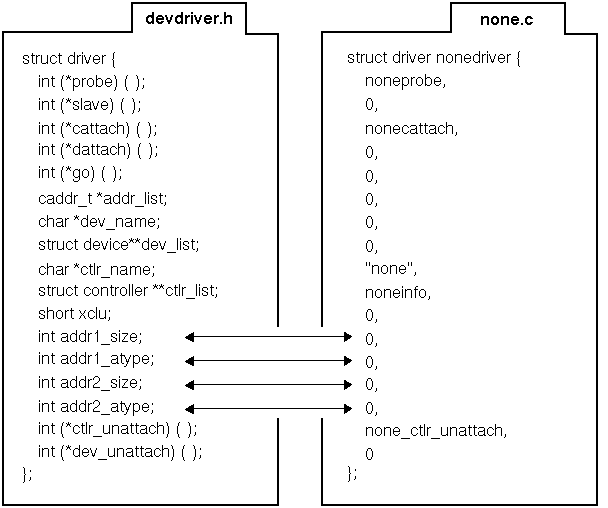
The addr2_size member specifies the size (in bytes) of the second CSR area. This area is usually the data area that the system uses with devices that have two separate CSR areas. Only drivers operating on the VMEbus use this member. The addr2_atype member specifies the address space, access mode, transfer size, and swap mode of the second CSR area. Note that not all bus adapters use the transfer size. Only drivers operating on the VMEbus use this member. Figure 5-7 shows that the driver writer initializes these members to the value zero (0) to indicate that they are not used by the /dev/none driver.
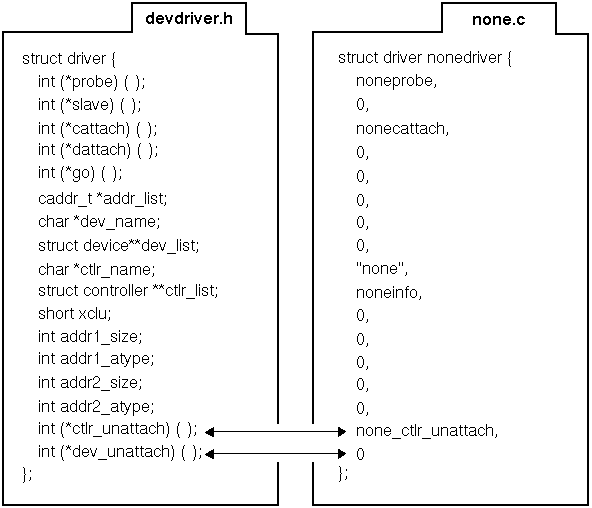
The ctlr_unattach member specifies a pointer to the controller's unattach interface. Dynamically configured drivers use the controller unattach interface. The dev_unattach member specifies a pointer to the device's unattach interface. Dynamically configured drivers use the device unattach interface. Figure 5-8 shows that the driver writer initializes the ctlr_unattach member to the interface none_ctlr_unattach. The driver writer initializes the dev_unattach member to the value zero (0) to indicate that there is no device unattach interface.
The device switch, or dsent, structure contains device driver entry points (and other information) for a specific character and block device. A device driver declares an instance of and sets to appropriate values the members of a dsent structure. A driver registers the information contained in the dsent structure and reserves an associated major number by calling the devsw_add interface. The kernel maintains a table of these dsent structures and their associated major numbers.
Section 5.2 shows how to declare and initialize an instance of the dsent structure, using the /dev/none driver as an example.
The following code shows the dsent structure defined in /usr/sys/include/sys/conf.h:
struct dsent
{
  int (*d_open)();
  int (*d_close)();
  int (*d_strategy)();
  int (*d_read)();
  int (*d_write)();
  int (*d_ioctl)();
  int (*d_dump)();
  int (*d_psize)();
  int (*d_stop)();
  int (*d_reset)();
  int (*d_select)();
  int (*d_mmap)();
  int (*d_segmap)();
  struct tty *d_ttys;
  int d_funnel;
  int d_bflags;
  int d_cflags;
};
The following sections discuss the members of the dsent structure. Section 6.6.5.2 shows how to call the devsw_add interface to register the entry points for the I/O services interfaces (and other information) for block and character drivers and to reserve an associated major number.
The d_open member specifies a pointer to an entry point for the block and character driver's open interface, which opens a device. Section 10.1.1 shows how to set up an open interface, using the /dev/none driver as an example.
The d_close member specifies a pointer to an entry point for the block and character driver's close interface, which closes a device. Section 10.1.1 shows how to set up a close interface, using the /dev/none driver as an example.
The d_strategy member specifies a pointer to an entry point for the block driver's strategy interface, which reads and writes block data. Section 9.3.6 shows how to set up a strategy interface, using the /dev/xx driver as an example.
Although the strategy interface applies to block device drivers, character device drivers can also contain a strategy interface that the character driver's read and write interfaces call. For example, VMEbus device drivers are typically character drivers and their read and write interfaces can use the physio interface. The physio interface performs the appropriate read or write operation (programmed I/O, VMEbus adapter hardware DMA, or device DMA). One of the parameters passed to the physio interface is the driver's strategy interface.
The d_read member specifies a pointer to an entry point for the character driver's read interface, which reads characters or raw data. Section 8.1.3 discusses how to set up a read interface, using the /dev/none driver as an example.
The d_write member specifies a pointer to an entry point for the character driver's write interface, which writes characters or raw data. Section 8.2 discusses how to implement a write interface, using the /dev/none driver as an example.
The d_ioctl member specifies a pointer to an entry point for the block and character driver's ioctl interface, which performs special functions or I/O control. Section 10.3 discusses how to set up an ioctl interface, using the /dev/none driver as an example.
The d_dump member specifies a pointer to an entry point for a block driver's dump interface, which is used for panic dumps of the system image. Section 10.3 discusses how to set up a dump interface, using the /dev/xx driver as an example.
The d_psize member specifies a pointer to an entry point for the block driver's psize interface, which returns the size in physical blocks of a device (disk partition). Section 9.2 discusses how to set up a psize interface, using the /dev/xx driver as an example.
The d_stop member specifies a pointer to an entry point for the driver's stop interface, which suspends other processing on behalf of the current process. You typically use the d_stop member only for terminal (character) drivers. Section 8.5.1 discusses how to set up a stop interface, using the /dev/xx driver as an example.
The d_reset member specifies a pointer to an entry point for the character driver's reset interface, which stops all current work and places the device connected to the controller in a known, quiescent state. Section 10.3 discusses how to set up a reset interface, using the /dev/xx driver as an example.
The d_select member specifies a pointer to an entry point for the character driver's select interface, which determines if a call to a read or write interface will block. Section 8.4 discusses how to implement a select interface, using the /dev/xx driver as an example.
The d_mmap member specifies a pointer to an entry point for the character driver's mmap interface, which maps kernel memory to user address space. Section 8.6 discusses how to set up a memory map interface, using the /dev/xx driver as an example.
The d_segmap member specifies the character driver's segmap entry point.
The d_ttys member specifies a pointer to the character driver's private data.
The d_funnel member schedules block and character device drivers onto a CPU in a multiprocessor configuration. You set this member to one of the following constants:
| Value | Meaning |
| DEV_FUNNEL |
Specifies that you want to funnel the device driver
because you have not made it SMP safe.
This means that the driver is forced to execute on a single (the
master) CPU.
Even if you funnel your device driver, you must follow the SMP locking conventions when accessing kernel data structures external to the driver. Typically, you use kernel interfaces that Digital supplies to indirectly access kernel data structures outside the driver. |
| DEV_FUNNEL_NULL | Specifies that you do not want to funnel the device driver because you have made it SMP safe. This means that the driver can execute on multiple CPUs. You make a device driver SMP safe by using the simple or complex lock mechanism. |
Writing Device Drivers: Advanced Topics provides information on how to write SMP-safe device drivers.
The d_bflags member specifies a block driver's device-related and other flags. You set this member to the bitwise inclusive OR of the device-related and other flags. One example of a device-related flag is B_TAPE. This flag is set in the b_flags member of the buf structure. The B_TAPE flag determines whether to use delayed writes, which are not allowed for tape devices. For all other drivers, this member is set to the value zero (0).
Another flag specifies whether this character driver is an SVR4 DDI/DKI-compliant device driver. You set this member to the B_DDIDKI flag to indicate that this is an SVR4 DDI/DKI-compliant device driver.
The d_cflags member specifies whether this character driver is an SVR4 DDI/DKI-compliant device driver. Set this member to the C_DDIDKI constant to indicate that this is an SVR4 DDI/DKI-compliant device driver.