This chapter discusses the kernel interfaces most commonly used by device drivers and provides code fragments to illustrate how to call these interfaces in device drivers. These code fragments and associated descriptions supplement the reference page descriptions for these and the other kernel interfaces presented in Writing Device Drivers: Reference. Specifically, the chapter discusses the following:
String interfaces allow device drivers to:
The following sections describe the kernel interfaces that perform these tasks.
To compare two null-terminated character strings, call the strcmp interface. The following code fragment shows a call to strcmp:
.
.
.

register struct device *device;
struct controller *ctlr;

.
.
.

if (strcmp(device->ctlr_name, ctlr->ctlr_name)) { [1]

.
.
.

}
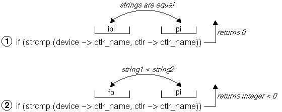
The code fragment sets up a condition statement that performs some tasks based on the results of the comparison. Figure 18-1 shows how strcmp compares two sample character string values in the code fragment. In item 1, strcmp compares the two controller names and returns the value zero (0) because strcmp performed a lexicographical comparison between the two strings and they were identical.
In item 2, strcmp returns an integer that is less than zero because the lexicographical comparison indicates that the characters in the first controller name, fb, come before the letters in the second controller name, ipi. [Return to example]
To compare two strings by using a specified number of characters, call the strncmp interface. The following code fragment shows a call to strncmp:
.
.
.

register struct device *device;

.
.
.

if( (strncmp(device->dev_name, "rz", 2) == 0)) [1]

.
.
.
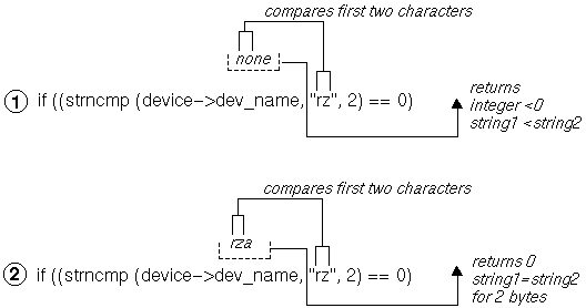
The code fragment sets up a condition statement that performs some tasks based on the results of the comparison. Figure 18-2 shows how strncmp compares two sample character string values in the code fragment. In item 1, strncmp compares the first two characters of the device name none with the string rz and returns an integer less than the value zero (0). The reason for this is that strncmp makes a lexicographical comparison between the two strings and the string no comes before the string rz. In item 2, strncmp compares the first two characters of the device name rza with the string rz and returns the value zero (0). The reason for this is that strncmp makes a lexicographical comparison between the two strings and the string rz is equal to the string rz. [Return to example]
To copy a null-terminated character string, call the strcpy interface. The following code fragment shows a call to strcpy:
.
.
.

struct tc_slot  tc_slot[TC_IOSLOTS]; [1]
char curr_module_name[TC_ROMNAMLEN + 1]; [2]

.
.
.

strcpy(tc_slot[i].modulename, curr_module_name); [3]

.
.
.
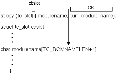
Figure 18-3 shows how strcpy copies a sample value in the code fragment. The interface copies the string CB (the value contained in curr_module_name) to the modulename member of the tc_slot structure associated with the specified bus. This member is presumed large enough to store the character string. The strcpy interface returns the pointer to the location following the end of the destination buffer. [Return to example]
To copy a null-terminated character string with a specified limit, call the strncpy interface. The following code fragment shows a call to strncpy:
.
.
.

register struct device *device;
char * buffer;

.
.
.

strncpy(buffer, device->dev_name, 2); [1]
if (buffer == somevalue)

.
.
.
The code fragment sets up a condition statement that performs some tasks based on the characters stored in the pointer to the buffer variable.
Figure 18-4 shows how strncpy copies a sample value in the code fragment. The interface copies the first two characters of the string none (the value pointed to by the dev_name member of the pointer to the device structure). The strncpy interface stops copying after it copies a null character or the number of characters specified in the third argument, whichever comes first.
The figure also shows that strncpy returns a pointer to the /NULL character at the end of the first string (or to the location following the last copied character if there is no NULL). The copied string will not be null terminated if its length is greater than or equal to the number of characters specified in the third argument. [Return to example]

To return the number of characters in a null-terminated character string, call the strlen interface. The following code fragment shows a call to strlen:
.
.
.

char *strptr;

.
.
.

if ((strlen(strptr)) > 1) [1]

.
.
.
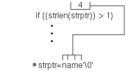
The code fragment sets up a condition statement that performs some tasks based on the length of the string. Figure 18-5 shows how strlen checks the number of characters in a sample string in the code fragment. As the figure shows, strlen returns the number of characters pointed to by the strptr variable, which in the code fragment is four. Note that strlen does not count the terminating null character. [Return to example]
The data copying interfaces allow device drivers to:
The following sections describe the kernel interfaces that perform these tasks.
To copy a series of bytes with a specified limit, call the bcopy interface. The following code fragment shows a call to bcopy:
.
.
.

struct tc_slot  tc_slot[TC_IOSLOTS]; [1]

.
.
.

char *cp; [2]

.
.
.


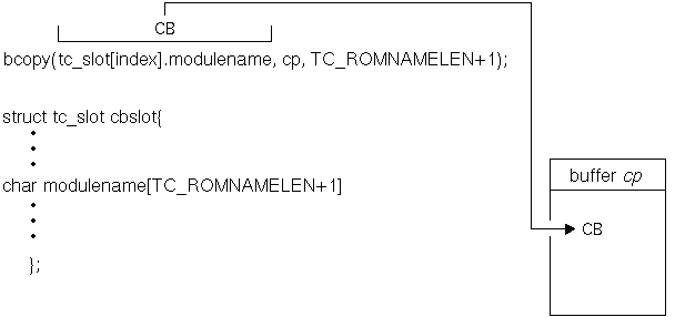
bcopy(tc_slot[index].modulename, cp, TC_ROMNAMLEN + 1); [3]

.
.
.
Figure 18-6
shows how
bcopy
copies a series of bytes by using a sample value in the code fragment.
As the figure shows,
bcopy
copies the characters
CB
to the buffer
cp.
No check is made for null bytes.
The copy is nondestructive; that is, the address ranges of
the first two arguments can overlap.
[Return to example]
To zero a block of memory, call the bzero or blkclr interface. The following code fragment shows a call to bzero. (The blkclr interface has the same arguments.)
.
.
.

struct bus *new_bus;

.
.
.

bzero(new_bus, sizeof(struct bus)); [1]

.
.
.
In the example, bzero zeros the number of bytes associated with the size of the bus structure, starting at the address specified by new_bus.
The blkclr interface performs the equivalent task. [Return to example]
To copy data from the unprotected user address space to the protected kernel address space, call the copyin interface. The following code fragment shows a call to copyin:
.
.
.

register struct buf *bp;
int err;
caddr_t buff_addr;
caddr_t kern_addr;

.
.
.

if (err = copyin(buff_addr,kern_addr,bp->b_resid)) { [1]

.
.
.
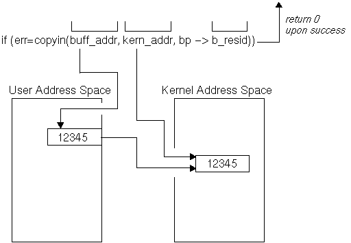
The code fragment sets up a condition statement that performs some tasks based on whether copyin executes successfully. Figure 18-7 shows how copyin copies data from user address space to kernel address space by using sample data.
As the figure shows,
copyin
copies the data from the unprotected user address space,
starting at the address specified by
buff_addr
to the protected kernel address space specified by
kern_addr.
The number of bytes is indicated by the
b_resid
member.
The figure also shows that
copyin
returns the value zero (0) upon successful completion.
If the address in user address space could not be accessed,
copyin
returns the error
EFAULT.
[Return to example]
To copy data from the protected kernel address space to the unprotected user address space, call the copyout interface. The following code fragment shows a call to copyout:
.
.
.

register struct buf *bp;
int err;
caddr_t buff_addr;
caddr_t kern_addr;

.
.
.

if (err = copyout(kern_addr,buff_addr,bp->b_resid)) { [1]

.
.
.
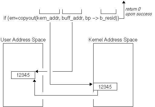
Figure 18-8 shows the results of copyout, based on the code fragment. As the figure shows, copyout copies the data from the protected kernel address space, starting at the address specified by kern_addr to the unprotected user address space specified by buff_addr. The number of bytes is indicated by the b_resid member. The figure also shows that copyout returns the value zero (0) upon successful completion. If the address in kernel address space could not be accessed or if the number of bytes to copy is invalid, copyout returns the error EFAULT. [Return to example]
To move data between user virtual space and system virtual space, call the uiomove interface. The following code fragment shows a call to uiomove:
.
.
.

struct uio *uio;
register struct buf *bp;
int err;
int cnt;
unsigned tmp;

.
.
.

err = uiomove(&tmp,cnt,uio); [1]

.
.
.
The hardware-related interfaces allow device drivers to perform the following tasks related to the hardware:
The following sections describe the kernel interfaces that perform these tasks.
To delay the calling interface a specified number of microseconds, call the DELAY interface. The following code fragment shows a call to this interface:
.
.
.

DELAY(10000) [1]

.
.
.
The DELAY interface delays the calling interface a specified number of microseconds. DELAY spins, waiting for the specified number of microseconds to pass before continuing execution. In the example, there is a 10000-microsecond (10-millisecond) delay. The range of delays is system dependent, due to its relation to the granularity of the system clock. The system defines the number of clock ticks per second in the hz variable. Specifying any value smaller than 1/hz to the DELAY interface results in an unpredictable delay. For any delay value, the actual delay may vary by plus or minus one clock tick.
Using the DELAY interface is discouraged because the processor will be consumed for the specified time interval and therefore is unavailable to service other processes. In cases where device drivers need timing mechanisms, you should use the sleep and timeout interfaces instead of the DELAY interface. The most common usage of the DELAY interface is in the system boot path. Using DELAY in the boot path is often acceptable because there are no other processes in contention for the processor. [Return to example]
To set the interrupt priority level (IPL) mask to a specified level, call one of the spl interfaces. Table 18-1 summarizes the uses for the different spl interfaces.
| spl Interface | Meaning |
| getspl | Gets the spl value. |
| splbio | Masks all disk and tape controller interrupts. |
| splclock | Masks all hardware clock interrupts. |
| spldevhigh | Masks all device and software interrupts. |
| splextreme | Blocks against all but halt interrupts. |
| splhigh | Masks all interrupts except for realtime devices, machine checks, and halt interrupts. |
| splimp | Masks all Ethernet hardware interrupts. |
| splnet | Masks all network software interrupts. |
| splnone | Unmasks (enables) all interrupts. |
| splsched | Masks all scheduling interrupts (usually the hardware clock). |
| splsoftclock | Masks all software clock interrupts. |
| spltty | Masks all tty (terminal device) interrupts. |
| splvm | Masks all virtual memory clock interrupts. |
| splx | Resets the CPU priority to the level specified by the argument. |
The spl interfaces set the CPU priority to various interrupt levels. The current CPU priority level determines which types of interrupts are masked (disabled) and which are unmasked (enabled). Historically, seven levels of interrupts were supported, with eight different spl interfaces to handle the possible cases. For example, calling spl0 would unmask all interrupts and calling spl7 would mask all interrupts. Calling an spl interface between 0 and 7 would mask all interrupts at that level and at all lower levels.
Specific interrupt levels were assigned for different device types. For example, before handling a given interrupt, a device driver would set the CPU priority level to mask all other interrupts of the same level or lower. This setting meant that the device driver could be interrupted only by interrupt requests from devices of a higher priority.
Digital UNIX currently supports the naming of spl interfaces to indicate the associated device types. Named spl interfaces make it easier to determine which interface you should use to set the priority level for a given device type.
The following code fragment shows the use of
spl
interfaces as part of a disk
strategy
interface:
.
.
.

int s;

.
.
.

s = splbio(); [1]

.
.
.

[Code to deal with data that can be modified by the disk interrupt
code]
splx(s); [2]

.
.
.
The binding of any spl interface with a specific CPU priority level is highly machine dependent. With the exceptions of the splhigh and splnone interfaces, knowledge of the explicit bindings is not required to create new device drivers. You always use splhigh to mask (disable) all interrupts and splnone to unmask (enable) all interrupts. [Return to example]
The kernel-related interfaces allow device drivers to:
The following sections describe the kernel interfaces that perform these tasks.
To print text to the console terminal and the error logger, call the printf interface. The kernel printf interface is a scaled-down version of the C library printf interface. The printf interface prints diagnostic information directly on the console terminal and writes ASCII text to the error logger. Because printf is not interrupt driven, all system activities are suspended when you call it. Only a limited number of characters (currently 128) can be sent to the console display during each call to any section of a driver. The reason is that the characters are buffered until the driver returns to the kernel, at which time they are actually sent to the console display. If more than 128 characters are sent to the console display, the storage pointer may wrap around, discarding all previous characters; or it may discard all characters following the first 128.
If you need to see the results on the console terminal, limit the message size to the maximum of 128 whenever you send a message from within the driver. However, printf also stores the messages in an error log file. You can use the uerf command to view the text of this error log file. See the reference page for this command. The messages are easier to read if you use uerf with the -o terse option.
The following code fragment shows a call to this interface:
.
.
.

#ifdef CB_DEBUG
printf("CBprobe @ %8x, vbaddr = %8x, ctlr = %8x\n",cbprobe,vbaddr,ctlr); [1]
#endif /*CB_DEBUG*/

.
.
.
The example shows that printf takes two arguments:
Digital UNIX also supports the uprintf interface. The uprintf interface prints to the current user's terminal. Interrupt service interfaces should never call uprintf. It does not perform any space checking, so you should not use this interface to print verbose messages. The uprintf interface does not log messages to the error logger. [Return to example]
To put a calling process to sleep, call the sleep interface. The sleep and wakeup interfaces block and then wake up a process. Generally, device drivers call these interfaces to wait for the transfer to complete an interrupt from the device. That is, the write interface of the device driver sleeps on the address of a known location, and the device's interrupt service interface wakes the process when the device interrupts. It is the responsibility of the wakened process to check if the condition for which it was sleeping has been removed. The following code fragment shows a call to this interface:
.
.
.

sleep(&ctlr->bus_name, PCATCH); [1]

.
.
.
To wake up all processes sleeping on a specified address, call the wakeup interface. The following code fragment shows a call to this interface:
.
.
.

wakeup(&ctlr->bus_name); [1]

.
.
.
To initialize a callout queue element, call the timeout interface. The following code fragment shows a call to this interface:
.
.
.

#define NONEIncSec  1

.
.
.

cb = &none_unit[unit];

.
.
.

timeout(noneincled, (caddr_t)none, NONEIncSec*hz); [1]


.
.
.
To remove the scheduled interfaces from the callout queues, call the untimeout interfaces. The following code fragment shows a call to this interface:
.
.
.

untimeout(noneincled, (caddr_t)none); [1]

.
.
.
The argument is used to uniquely identify which timeout to remove. This is useful if more than one process has called timeout with the same interface argument. [Return to example]
As discussed in Section 2.3.1, you use the I/O handle to provide device driver binary compatibility across different bus architectures, different CPU architectures, and different CPU types within the same CPU architecture. The following categories of kernel interfaces use an I/O handle:
The following sections discuss how the interfaces associated with each category use the I/O handle.
Digital UNIX provides several generic interfaces to copy a block of memory to or from I/O space. These generic interfaces map to bus- and machine-specific interfaces that actually perform the copy operation. Using these interfaces to copy a block of memory to or from I/O space makes the device driver more portable across different CPU architectures and different CPU types within the same architecture. These generic interfaces allow device drivers to:
Each of these interfaces is discussed in the following sections.
To copy data from bus address space to system memory, call the io_copyin interface. The io_copyin interface is a generic interface that maps to a bus- and machine-specific interface that actually performs the copy from bus address space to system memory. Using io_copyin to perform the copy operation makes the device driver more portable across different CPU architectures and different CPU types within the same architecture.
The following code fragment shows a call to io_copyin to copy the memory block:
.
.
.

struct xx_softc {

.
.
.

    io_handle_t iohandle; [1]


.
.
.

};

.
.
.

xxprobe(iohandle, ctlr)
 io_handle_t iohandle; [2]
 struct controller *ctlr;
{
  register struct xx_softc *sc; [3]
  int ret_val; [4]

.
.
.

 sc->iohandle = iohandle; [5]

.
.
.

xxwrite(dev, uio, flag)
 dev_t dev;
 register struct uio *uio;
 int flag;
{
 char * buf;
 buf = (char *)MALLOC(PAGE_SIZE, char*, sizeof(PAGE_SIZE),
                      M_DEVBUF, M_NOWAIT);
 ret_val = io_copyin(sc->iohandle, buf, PAGE_SIZE); [6]

.
.
.

}
The io_copyin interface takes three arguments:
In the example, the I/O handle passed to io_copyin is the one passed to xxprobe and stored in the iohandle member of the sc pointer.
The example calls the MALLOC interface to allocate the memory for the kernel virtual address where io_copyin copies the data to in-system memory.
The example uses the PAGE_SIZE constant for the number of bytes in the memory block to be copied.
Upon successful completion, io_copyin returns IOA_OKAY. It returns the value -1 on failure.
To copy data from system memory to bus address space, call the io_copyout interface. The io_copyout interface is a generic interface that maps to a bus- and machine-specific interface that actually performs the copy to bus address space. Using io_copyout to perform the copy operation makes the device driver more portable across different CPU architectures and different CPU types within the same architecture.
The following code fragment shows a call to io_copyout to copy the memory block:
.
.
.

struct xx_softc {

.
.
.

    io_handle_t iohandle; [1]

.
.
.

};

.
.
.

xxprobe(iohandle, ctlr)
 io_handle_t iohandle; [2]
 struct controller *ctlr;
{
  register struct xx_softc *sc; [3]
  int ret_val; [4]

.
.
.

 sc->iohandle = iohandle; [5]

.
.
.

xxwrite(dev, uio, flag)
 dev_t dev;
 register struct uio *uio;
 int flag;
{
 char * buf;
 buf = (char *)MALLOC(PAGE_SIZE, char*, sizeof(PAGE_SIZE),
                      M_DEVBUF, M_NOWAIT);
 ret_val = io_copyout(buf, sc->iohandle, PAGE_SIZE); [6]

.
.
.

}
The io_copyout interface takes three arguments:
The example calls the MALLOC interface to obtain the kernel virtual address where the copy originates in system memory.
In the example, the I/O handle passed to io_copyout is the one passed to xxprobe and stored in the iohandle member of the sc pointer.
The example calls the MALLOC interface to allocate the memory for the kernel virtual address where io_copyout copies the data to the bus address space. The example uses the PAGE_SIZE constant for the number of bytes in the memory block to be copied.
Upon successful completion, io_copyout returns IOA_OKAY. It returns the value -1 on failure.
To copy data from one location in bus address space to another location in bus address space, call the io_copyio interface. The io_copyio interface is a generic interface that maps to a bus- and machine-specific interface that actually performs the copy of data from one location in bus address space to another location in bus address space. Using io_copyio to perform the copy operation makes the device driver more portable across different CPU architectures and different CPU types within the same architecture.
The following code fragment shows a call to io_copyio to copy the memory block:
.
.
.

struct xx_softc { [1]

.
.
.

    io_handle_t src_addr;
    io_handle_t dest_addr;


.
.
.

};

.
.
.

xxprobe(xxprobe_iohandle, ctlr)
 io_handle_t xxprobe_iohandle; [2]
 struct controller *ctlr;
{
  register struct xx_softc *sc; [3]
  int ret_val; [4]

.
.
.

 sc->src_addr = xxprobe_iohandle; [5]
 sc->dest_addr = xxprobe_iohandle + 0x0400; [6]

.
.
.

xxwrite(dev, uio, flag)
 dev_t dev;
 register struct uio *uio;
 int flag;
{
 ret_val = io_copyio(sc->src_addr, sc->dest_addr, PAGE_SIZE); [7]

.
.
.

}
The io_copyio interface takes three arguments:
In the example, the I/O handle passed to io_copyio is the one passed to xxprobe and stored in the src_addr member of the sc pointer.
Upon successful completion, io_copyio returns IOA_OKAY. It returns the value -1 on failure.
As discussed in Section 3.1.3, one of the issues that influences device driver design is the technique for performing direct memory access (DMA) operations. Whenever possible, you should design device drivers so that they can accommodate DMA devices connected to different buses operating on a variety of Alpha CPUs. The different buses can require different methods for accessing bus I/O addresses and the different Alpha CPUs can have a variety of DMA hardware support features.
To help you overcome the differences in DMA operations across the different buses and Alpha CPUs, Digital UNIX provides a package of mapping interfaces. The mapping interfaces provide a generic abstraction to the kernel- and system-level mapping data structures and to the mapping interfaces that actually perform the DMA transfer operation. This work includes acquiring the hardware and software resources needed to map contiguous I/O bus addresses (accesses) into discontiguous system memory addresses (accesses).
Using the mapping interfaces makes device drivers more portable between major releases of Digital UNIX (and different hardware support for I/O buses) because it masks out any future changes in the kernel- and system-level DMA mapping data structures. Specifically, these interfaces allow you to:
The DMA mapping package also provides convenience interfaces that allow you to:
The following sections describe the kernel interfaces that perform these tasks and also discuss the DMA handle and the sg_entry data structure associated with these DMA interfaces.
To provide device driver binary compatibility across different bus architectures, different CPU architectures, and different CPU types within the same CPU architecture, Digital UNIX represents DMA resources through a DMA handle. A DMA handle is a data entity that is of type dma_handle_t. This handle provides the information to access bus address/byte count pairs. Device driver writers can view the DMA handle as the tag to the allocated system resources needed to perform a DMA operation.
The sg_entry data structure contains two members: ba and bc. These members represent a bus address/byte count pair for a contiguous block of an I/O buffer mapped onto a controller's bus memory space. The byte count indicates the number of bytes that the address is contiguously valid for on the controller's bus address space. Consider a list entry that has its ba member set to aaaa and its bc member set to nnnn. In this case, the device can perform a contiguous DMA data transfer starting at bus address aaaa and ending at bus address aaaa+nnnn-1.
Table 18-2 lists the members of the sg_entry structure along with their associated data types.
| Member Name | Data Type |
| ba | bus_addr_t |
| bc | u_long |
The ba member stores an I/O bus address.
The bc member stores the byte count associated with the I/O bus address. This byte count indicates the contiguous addresses that are valid on this bus.
To allocate resources for DMA data transfers, call the dma_map_alloc interface. Using the dma_map_alloc interface makes device drivers more portable between DMA hardware-mapping implementations across different hardware platforms because it masks out any future changes in the kernel- and system-level DMA mapping data structures.
The following code fragment taken from a /dev/fd device driver shows the four arguments associated with the call to dma_map_alloc. Two of the arguments passed to dma_map_alloc are defined as members of an fdcam_class data structure.
.
.
.

#define SECTOR_SIZE 512

.
.
.

struct fdcam_class {

.
.
.

dma_handle_t fc_dma_handle;

.
.
.

struct controller *ctlr;
};

.
.
.

  struct fdcam_class* fcp = &fc_0;

.
.
.

 if (dma_map_alloc(SECTOR_SIZE, fcp->ctlr, &fcp->fc_dma_handle,
                   DMA_SLEEP) == 0) { [1]

.
.
.
In this example, the byte_count is the value defined by the SECTOR_SIZE constant.
In this example, ctlr_p is the value stored in the ctlr member. Assume that the /dev/fd driver previously set the ctlr member to the controller structure pointer associated with this device at probe time.
In this example, the DMA handle appears as a member in the fdcam_class data structure.
In this example, the bit represented by the DMA_SLEEP constant is passed. This bit puts the process to sleep if the system cannot allocate the necessary resources to perform a data transfer of size byte_count at the time the driver calls the interface.
The code fragment sets up a condition statement that performs some tasks based on the value returned by dma_map_alloc. Upon successful completion, dma_map_alloc returns a byte count (in bytes) that indicates the DMA transfer size it can map. It returns the value zero (0) to indicate a failure.
To load and set allocated system resources for DMA data transfers, call the dma_map_load interface. The dma_map_load interface is a generic interface that maps to a bus- and machine-specific interface that actually performs the loading and setting of system resources for DMA data transfers. Using this interface in DMA read and write operations makes the device driver more portable across different bus architectures, different CPU architectures, and different CPU types within the same CPU architecture.
The following code fragment taken from a /dev/fd device driver shows the seven arguments associated with the call to dma_map_load. Note that the arguments passed to dma_map_load are defined as members of an fdcam_class data structure. The /dev/fd driver shows an example of fixed preallocated DMA resources.
.
.
.

#define SECTOR_SIZE 512

.
.
.

struct fdcam_class {

.
.
.

int rw_count;
unsigned char *rw_buf;
struct proc *rw_proc;
dma_handle_t dma_handle;

.
.
.

struct controller *ctlr;
};

.
.
.

  struct fdcam_class* fcp = fsb->fcp;

.
.
.

  flags = (fcp->rw_op == OP_READ) ? DMA_IN : DMA_OUT;
  if (dma_map_load(fcp->rw_count * SECTOR_SIZE, fcp->rw_buf,
                   fcp->rw_proc, fcp->ctlr, &fcp->dma_handle, 0,
                   flags) == 0) { [1]

.
.
.
In this example, the size is the result of the SECTOR_SIZE and the value stored in rw_count. Assume that the /dev/fd driver previously set the rw_count member to some value.
In this example, ctlr_p is the value stored in the ctlr member. Assume that the /dev/fd driver previously set the ctlr member to the controller structure pointer associated with this device at probe time.
In this example, the /dev/fd device driver simply passes the address of the DMA handle that is a member of the fdcam_class structure.
In this example, the /dev/fd driver passes the value zero (0).
In this example, flags is DMA_IN if rw_op evaluates to TRUE (that is, this is a DMA read operation). The DMA_IN bit indicates that the system should perform a DMA write into core memory. Otherwise, flags is DMA_OUT if rw_op evaluates to FALSE (that is, this is a DMA write operation). The DMA_OUT bit indicates that the system should perform a DMA read from the main core memory.
The code fragment sets up a condition statement that performs some tasks based on the value returned by dma_map_load. Upon successful completion, dma_map_load returns a byte count (in bytes) that indicates the DMA transfer size it can support. It returns the value zero (0) to indicate a failure.
To unload the resources that were loaded and set up in a previous call to dma_map_load, call the dma_map_unload interface. The dma_map_unload interface is a generic interface that maps to a bus- and machine-specific interface that actually performs the unloading of system resources associated with DMA data transfers. Using this interface in DMA read and write operations makes the device driver more portable across different bus architectures, different CPU architectures, and different CPU types within the same CPU architecture.
The following code fragment taken from a /dev/fd device driver shows the two arguments associated with the call to dma_map_unload. One of the arguments passed to dma_map_unload is defined as a member of an fdcam_class data structure.
.
.
.

struct fdcam_class {

.
.
.

char rw_use_dma;

.
.
.

dma_handle_t dma_handle;

.
.
.

};

.
.
.

  struct fdcam_class* fcp = fsb->fcp;

.
.
.

  if (fcp->rw_use_dma) {
      dma_map_unload(0, fcp->dma_handle);
  } [1]

.
.
.
In this example, the /dev/fd driver passes the value zero (0) to indicate that it did not want to deallocate the DMA mapping resources.
In this example, the /dev/fd device driver simply passes the DMA handle that is a member of the fdcam_class structure.
The code fragment sets up a condition statement that calls dma_map_unload if the rw_use_dma evaluates to a nonzero (true) value. Upon successful completion, dma_map_unload returns the value 1. Otherwise, it returns the value zero (0).
A call to dma_map_unload does not release or deallocate the resources that were allocated in a previous call to dma_map_alloc unless the driver sets the flags argument to the DMA_DEALLOC bit.
To release and deallocate the resources that were allocated in a previous call to dma_map_alloc, call the dma_map_dealloc interface. Using the dma_map_dealloc interface makes device drivers more portable between DMA hardware-mapping implementations across different hardware platforms because it masks out any future changes in the kernel- and system-level DMA mapping data structures.
The following code fragment taken from a /dev/fd device driver shows the argument associated with the call to dma_map_dealloc. This argument is defined as a member of an fdcam_class data structure.
.
.
.

struct fdcam_class {

.
.
.

char rw_use_dma;

.
.
.

dma_handle_t dma_handle;

.
.
.

};

.
.
.

struct fdcam_class* fcp;

.
.
.

  if (fcp->rw_use_dma) {
      dma_map_dealloc(fcp->dma_handle_p);
  } [1]

.
.
.
In this example, the /dev/fd device driver simply passes the DMA handle that is a member of the fdcam_class structure. [Return to example]
The code fragment sets up a condition statement that calls dma_map_dealloc if the rw_use_dma evaluates to a nonzero (true) value. Upon successful completion, dma_map_dealloc returns the value 1. Otherwise, it returns the value zero (0).
The DMA handle provides device drivers with a tag to the allocated system resources needed to perform a DMA operation. In particular, the handle provides the information for drivers to access bus address/byte count pairs. The system maintains arrays of sg_entry data structures. Some device drivers may need to traverse the arrays of sg_entry data structures to obtain specific bus address/byte count pairs. The DMA mapping package provides two convenience interfaces that allow you to traverse the discontinuous sets of sg_entry arrays:
The following example shows the similarities and differences between the calls to dma_get_curr_sgentry and dma_get_next_sgentry:
.
.
.
dma_handle_t dma_handle; [1] sg_entry_t sgentry_curr; [2] vm_offset_t address_curr; [3] long count_curr; [4]
.
.
.
sgentry_curr = dma_get_curr_sgentry(dma_handle) [5]
.
.
.
address_curr = (vm_offset_t)sgentry_curr->ba; [6] count_curr = sgentry_curr->bc - 1; [7]dma_handle_t dma_handle; [1] sg_entry_t sgentry_next; [2] vm_offset_t address_next; [3] long count_next; [4]
.
.
.
sgentry_next = dma_get_next_sgentry(dma_handle) [5]
.
.
.
address_next = (vm_offset_t)sgentry_next->ba; [6] count_next = sgentry_next->bc - 1; [7]
The DMA handle provides device drivers with a tag to the allocated system resources needed to perform a DMA operation. In particular, the handle provides the information for drivers to access bus address/byte count pairs. The system maintains arrays of sg_entry data structures. Some device drivers may need to traverse the arrays of sg_entry data structures to put new bus address/byte count pair values into the ba and bc members of specific sg_entry structures. The DMA mapping package provides two convenience interfaces that allow you to traverse the discontinuous sets of sg_entry arrays:
The following code fragment shows the similarities and differences between the calls to dma_put_curr_sgentry and dma_put_prev_sgentry:
.
.
.
dma_handle_t dma_handle; [1] sg_entry_t sgentry_curr; [2] int ret_curr; [3]
.
.
.
Call dma_map_load [4]
.
.
.
Call MALLOC [5]
.
.
.
Call dma_map_load a second time [6]
.
.
.
Set the ba & bc members [7]
.
.
.
ret_curr = dma_put_curr_sgentry(dma_handle, sgentry_curr) [8]
.
.
.
Call dma_map_dealloc [9]dma_handle_t dma_handle; [1] sg_entry_t sgentry_prev; [2] int ret_prev; [3]
.
.
.
Call dma_map_load [4]
.
.
.
Call kalloc [5]
.
.
.
Call dma_map_load a second time [6]
.
.
.
Set the ba & bc members [7]
.
.
.
ret_prev = dma_put_prev_sgentry(dma_handle, sgentry_prev) [8]
.
.
.
Call dma_map_dealloc [9]
To return a kernel segment (kseg) address of a DMA buffer, call the dma_kmap_buffer interface. The dma_kmap_buffer interface takes an offset variable and returns a kseg address. The device driver can use this kseg address to copy and save the data at the offset in the buffer. The following code fragment shows a call to dma_kmap_buffer:
.
.
.

dma_handle_t dma_handle;
u_long offset;
vm_offset_t kseg_addr;

.
.
.

kseg_addr = dma_kmap_buffer(dma_handle, offset) [1]
Upon successful completion, dma_kmap_buffer returns a kseg address of the byte offset pointed to by the addition of the following two values:
virt_addr + offset
where:
The dma_kmap_buffer interface returns the value zero (0) to indicate failure to retrieve the kseg address.
The miscellaneous interfaces allow device drivers to:
The following sections describe the kernel interfaces that perform these tasks.
To indicate that I/O is complete, call the iodone interface. The following code fragment shows a call to this interface. The code fragment verifies read or write access to the user's buffer before beginning the DMA operation.
.
.
.

{
                bp->b_error = EACCES;
                bp->b_flags |= B_ERROR;
                iodone(bp); [1]
                return;
               }

.
.
.
To implement raw I/O, call the physio interface. This interface maps the raw I/O request directly into the user buffer, without using bcopy. The memory pages in the user address space are locked while the transfer is processed.
The following code fragment shows a call to this interface:
.
.
.

return(physio(nonestrategy,none->nonebuf,dev,B_READ,noneminphys,uio)); [1]

.
.
.