![[Return to Library]](BOOKSHELF.GIF)
![[TOC]](TOC.GIF)
![[PREV]](REW.GIF)

![[NEXT]](FF.GIF)
![[INDEX]](INDEX.GIF)
![[Help]](HELP.GIF)
For detailed information on the VMEbus architecture, see the IEEE Standard for a Versatile Backplane Bus: VMEbus ANSI/IEEE Std 1014-1987.
These address spaces are overlapping and can be unique in the Digital
UNIX model; that is, an address (for example, 0xC0) points to the same location
in all three address spaces. Some VMEbus devices can respond to address requests
in any of the address spaces.
Some VMEbus adapters provide hardware byte
swapping. Digital's adapters may provide hardware assist for direct memory
access (DMA) transfers and programmed I/O (PIO) transfers on an
adapter-dependent basis.
Kernel interfaces and library calls accomplish
the byte swapping. Writing Device Drivers: Reference
presents, in reference page style, descriptions of the following byte-swapping
interfaces: swap_lw_bytes, swap_word_bytes,
and swap_words.
You supply interrupt vectors by specifying a
VBA_Option entry in the
/etc/sysconfigtab file or a
sysconfigtab file fragment.
Digital UNIX allows the adapter to handle any or all of the VMEbus interrupt
levels. In general, you will want the adapter to handle all seven levels.
If, however, there is another processor on the VMEbus that you want to handle
VMEbus interrupts, you can selectively enable the interrupts. The mechanism
for accomplishing this is adapter specific. See the documentation supplied
with the adapter for information on how to accomplish this.
VMEbus adapter-specific implementations can constrain DMA allocations
and I/O allocations for different address spaces within the 4 GB overmapped
region.
During device autoconfiguration, the VMEbus configuration code maps
the VMEbus IRQ level to a system priority level (SPL). The VMEbus configuration
code uses the priority member of the controller structure pointer associated with the device to store the SPL.
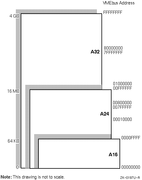
The figure shows the following overmapped address spaces:
Valid VMEbus CSR addresses for the A16 space range from 00000000 to
0000FFFF, inclusive.
Valid VMEbus CSR addresses for the A24 space range from 00000000 to 00FFFFFF,
inclusive.
Valid VMEbus CSR addresses for the A32 space range from 00000000 to FFFFFFFF,
inclusive.
In previous versions of the operating system, you allocate the VMEbus
address space for direct memory access operations by calling vballoc or vbasetup. For this version of Digital UNIX,
you must use the following interfaces:
Allocates resources for DMA data transfers
Loads and sets allocated DMA resources and sets up a DMA data path for
DMA data transfers
You can also use vba_set_dma_addr to specify a VMEbus
address and DMA flags for dma_map_alloc and dma_map_load.
The values that dma_map_alloc and dma_map_load return are different than those that vballoc
and vbasetup return. See Section 5.1
for examples of how to use dma_map_alloc and dma_map_load.
The host processor makes no further intervention during the transfer
of the data. Upon completion of the data transfer, the device controller interrupts
to indicate that the transfer has successfully completed. This is usually
referred to as inbound transfers of DMA read and write operations. The device
initiates the transfer of data and contains a DMA engine.
Consider the following when working with the VMEbus and DMA:
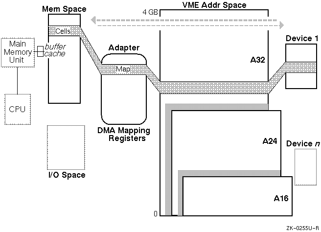
The figure depicts the following typical VMEbus environment:
The figure uses two arrows to indicate that the device initiates the
DMA data transfer operation: in one case a read operation and in the other
a write operation. In both cases, the host memory is mapped into the A32 space.
The transfer continues through the adapter into the host memory. Some memory
space in the CPU is mapped to the A32 DMA space.
In the case of the read operation, the device reads from the A32 mapped
space and the data is fetched by the device from mapped host memory.
Not all adapters provide the ability to perform DMA to the entire address
range.
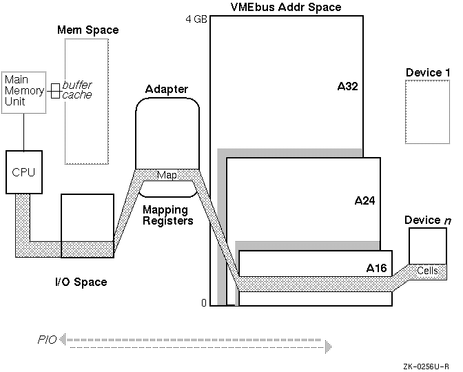
In the PIO mechanism, the device driver performs the
data transfer. The VMEbus address space for the CSRs or onboard memory is
mapped during VMEbus configuration when the device is configured. The sizes
and address spaces for the mapped areas are set in the following members of
the driver structure: addr1_size, addr2_size, addr1_atype, and addr2_atype. Section 4.2 describes these members
as they apply to the VMEbus. Digital UNIX passes the information contained
in these members to the device driver through the driver's probe interface.
Section 3.3.1
shows how to set up a probe interface for a VMEbus device
driver.
VMEbus device drivers can map outbound VMEbus address space by calling
the vba_map_csr interface.
Digital UNIX provides the following generic CSR I/O access interfaces
to read from and write to the device's CSR addresses: read_io_port and write_io_port. Digital recommends that all
new VMEbus device drivers call the read_io_port and write_io_port interfaces. The previously listed VMEbus-specific
interfaces are obsolete and no longer available. See Writing Device
Drivers: Tutorial for descriptions and examples of read_io_port and write_io_port.
![]()
2.1 VMEbus Hardware Architecture
The VMEbus,
like other buses, is a computer architecture that defines a computer data
path. Unlike other buses, the VMEbus is microprocessor independent, is easily
upgraded from 16-bit to 32-bit processors, and is suitable for a vendor to
build compatible products. The following VMEbus hardware architecture topics
are relevant to the device driver writer:

2.1.1 Address Spaces
The VMEbus hardware makes
no distinction between I/O space and memory space. The device driver writer
must understand which address space the board uses. The VMEbus hardware architecture
includes three address spaces:
2.1.2 Data Sizes
The VMEbus supports 8-bit (D08), 16-bit
(D16), and 32-bit (D32) data sizes.
A VMEbus device can
operate in more than one data space at one time. For example, a VMEbus device
may have D16 control registers and D32 memory.
2.1.3 Byte Ordering
While the VMEbus does not specify any
particular byte ordering, most devices use the Motorola model, which is big
endian.
Because the Digital model is little endian,
two mechanisms are provided to accomplish byte swapping:
2.1.4 Interrupt Vectors
VMEbus interrupt vectors range from 0x00 to 0xff, inclusive. Some
of these vectors are consumed by the bus adapter and not available for use
by device drivers.
Interrupt vectors that a controller can
use are VMEbus adapter specific. See the adapter-specific documentation for
more information.
2.1.5 Interrupt Priorities
The VMEbus provides for seven interrupt priorities (IRQ 1 through
IRQ 7, with IRQ 7 the highest priority).
On some host implementations,
fewer than seven levels may be provided. On those implementations, the VMEbus
priorities are mapped to the available host priority levels.Note
2.2 VMEbus Software Architecture
Before
writing device drivers that operate on the VMEbus, you need to consider the
following topics associated with the VMEbus software architecture:
2.2.1 VMEbus Address Space
The VMEbus supports as many
as 64 different address spaces.
Specific VMEbus adapter implementations
usually support a subset of these address spaces. In many of these implementations,
the address spaces overlap such that an address in one space is synonymous
with an address in a different space. For this reason, Digital UNIX overmaps
these address spaces onto a 4-gigabyte (GB) (32 address bits) space as shown
in Figure 2-1.
Figure 2-1: VMEbus Address Space
Note
Note
2.2.2 Direct Memory Access Support
Some VMEbus devices can perform
direct memory access (DMA).
The host processor informs the device controller
about the following when performing DMA:
2.2.2.1 VMEbus-to-Host DMA
Figure 2-2 shows
VMEbus-to-host DMA and VMEbus-from-host DMA.
Figure 2-2: VMEbus-to-Host DMA (Read and Write Operations)
2.2.2.2 VMEbus Device-to-Device DMA
In addition to VMEbus-to-host DMA (inbound transfer with respect
to the CPU), there is VMEbus device-to-device DMA. The VMEbus address space
may have holes that are created by device registers and onboard memory. VMEbus
device-to-device DMA on the current bus adapter must reside outside of any
system's inbound DMA configured window.
2.2.2.3 Rules for Performing DMA on Multiple VMEbus Adapters
The following list describes rules for performing
DMA operations on multiple VMEbus adpaters:
2.2.3 I/O Access
Applications
access I/O devices through memory locations in the physical address space
of the CPU. A programmed I/O (PIO) mechanism is provided for transferring
data as the result of a data transfer request from an application. Figure 2-3
shows programmed I/O.
Figure 2-3: Programmed I/O
2.2.4 Writes to the Hardware Device Register
Whenever
a VMEbus device driver writes to a hardware device register, the write might
be delayed by the system write buffer that is used to synchronize the CPU.
A subsequent read of that register does not wait for the write to be completed.
In previous versions of the operating system, you use VMEbus-specific interfaces
to accomplish all accesses to VMEbus address space. The vme_read_byte, vme_read_word, vme_read_long, vme_write_byte, vme_write_word, and vme_write_long interfaces let you read or write a byte, word, or
longword from or to the VMEbus address space.