An EISA configuration file defines all possible configuration options for an EISA or ISA board. Not only does it specify the resources that need to be allocated, such as interrupt channels and memory space, but it also defines an order of preference if several options are available for a particular resource. The EISA Configuration Utility (ECU) uses this information to create a conflict-free configuration. The resulting configuration is written to nonvolatile memory and saved on diskette.
As the ECU runs through the options in the configuration file, it allocates resources on a first-come, first-serve basis beginning with slot 1 and picking the first choice that is available. For example, if slot 1 can use either IRQ(1) or IRQ(4) (interrupt channels 1 and 4), the ECU assigns IRQ(1) to that slot. Later, if slot 4 requests IRQ(1), the ECU looks for another interrupt channel that slot 4 can use. If none is found, it assigns IRQ(4) to slot 1, making IRQ(1) available for slot 4.
If the ECU encounters a conflict that it cannot resolve, it notifies the user. The user must resolve the conflict by choosing which board to configure and which to remove.
The system startup procedure detects EISA boards at startup and checks their configuration information. If correct, the startup procedure loads the information into the system. If not correct, the startup procedure prompts the user to run the ECU.
The startup procedure cannot detect ISA boards. Therefore, it ignores ISA configuration information and assumes that it is correct. The user must be sure to run the ECU whenever new firmware is loaded onto the system or the configuration changes. Otherwise, the startup procedure may load incorrect configuration information.
This chapter describes how to write an EISA configuration file, from gathering the information you need before you write the file through running the ECU. The chapter uses examples from configuration files for an EISA Ethernet board, a Microsoft ISA sound board, and a generic ISA board. For a complete description of the configuration file format, see Appendix B.
You can take a configuration file written for another platform and migrate it to Digital UNIX. If you plan to do this, be aware of the following:
If no configuration file is available, you may write a new one. Before you begin, you need to obtain a copy of the manufacturer's hardware specifications, which contain the following information necessary for configuration:
Board IDs uniquely identify the board. These IDs have three parts:
The ECU uses the board ID to locate the correct configuration file. EISA boards have built-in board IDs. ISA boards do not, so you must assign an ID to the board in its configuration file. When users run the ECU, they must point to the correct file to configure the board.
Dynamic memory access (DMA) allows the board to address the memory that resides in system space. There are two types of DMA:
The specifications should state whether the board uses DMA, whether it is a master or slave board, and which channels the board can use.
Interrupts alert the system when a device has made a request. They are placed on one of several interrupt channels. Some boards allow more than one device to share an interrupt. You must find out the number of interrupts the board needs, which channels the interrupts can use, and whether they can be shared.
I/O space refers to the address space that the board can use for control and status registers and for low-speed data transfers (programmed I/O). The amount of space that is available, and whether that space must be reserved during configuration, is determined by the type of board. EISA boards have 4K of I/O space reserved for each slot, or 64K of total I/O address space. ISA boards must reserve addresses within a 1K address space shared among all slots on the system. The manufacturer's specifications should describe the board's I/O space requirements.
Some boards need additional memory for performing buffered I/O operations. The system treats the memory on all boards as one continuous address space. A memory map assigns address ranges to specific boards. You must define the size of memory space addresses (byte, word, or longword) and the type of memory (such as system, expansion board, or virtual memory) in the configuration file.
You may need to define other configuration options, as described in the specifications.
The following are the specifications for the EISA Ethernet board:
The board ID for the Digital model 422 Ethernet board, Revision 0, is dec4220.
This ethernet board does not use DMA.
The board needs one interrupt channel, either IRQ 5, 9, 10, or 11.
Two registers are defined within I/O space - one for a configuration register, the other for control and status registers.
The board can use either 64K or 32K bytes of memory space. The configuration file specifies two ranges of addresses for each size. The ECU reserves the first available space for the controller.
At configuration time, the user can choose whether to enable or disable remote bootup and remote timeout.
The user can also choose between thinwire and thickwire connection. After choosing the type of connection, the user must set the jumpers manually. The configuration file initializes an internal representation of the jumpers, which the ECU displays to help the user set them properly.
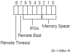
A configuration register saves the configuration choices made by the ECU and the user, as shown in Figure 9-1. The user's thinwire versus thickwire selection is not saved in the register.

The following are the specifications for the Microsoft ISA sound board:
The board ID for the Microsoft Sound board model 200, Revision 0, is ISA2000.
The board needs two DMA channels. Three paired combinations are possible: channels 0 and 1, 1 and 0, or 3 and 0.
The board needs one interrupt channel, either IRQ 7, 9, 10, or 11.
The board needs one I/O port.
This board does not have additional memory.
The generic ISA configuration file contains all possible configuration options.
When the ECU reads the board ID, it builds a configuration file name by adding an exclamation point to the beginning of the ID and the .cfg extension to the end of the ID. If the ECU cannot find a configuration file with that name on the ECU diskette, it replaces the exclamation point with the letter a and tries again. If the ECU still cannot find the file, it prompts the user to insert a floppy with the configuration file on it.
Within the configuration file, the board ID is specified in a BOARD identification block, which contains information such as the board's name and manufacturer.
The Digital 422 Ethernet board has a board ID of DEC4220. From this board ID, the ECU builds the configuration file name, !dec4220.cfg or adec4220.cfg.
BOARD
  ID = "DEC4220"
  NAME = "Digital EISA Ethernet Controller (DE422-SA)"
  MFR = "Digital Equipment Corporation"
  CATEGORY = "NET"
  SLOT = EISA
  AMPERAGE = 5000
  SKIRT = NO
  READID = YES
  IOCHECK = VALID
  DISABLE = SUPPORTED
The Microsoft sound board is an ISA board. Therefore, its board ID is not on the board itself. The user must point the ECU to the board's configuration file by selecting step 2: Add or Remove Boards and choosing the !isa2000.cfg configuration file.
BOARD
  ID="ISA2000"
  NAME="Microsoft Sound Board ISA Adapter Definition"
  MFR="Microsoft"
  CATEGORY="OTH"
  SLOT=ISA16
  LENGTH=150
The generic ISA configuration file can configure any ISA board. The board ID has no relation to the board being configured; it simply helps the user and the ECU locate the configuration file.
BOARD
  ID="ISA0000"
  NAME="Generic ISA Adapter Definition"
  MFR="Any manufacturer"
  CATEGORY="OTH"
  SLOT=ISA8OR16
  LENGTH=100   ; This allows the board to fit in almost any slot
  COMMENTS=
"Use this generic adapter definition to reserve the resources for any\n
ISA adpter for which a CFG file does not exist.\n\n
Determine the appropriate resource selections for IRQs, DMAs, port\n
addresses, and memory just as you would in any ISA computer system,\n
and select them manually during configuration as follows:\n
- Select 'Step 3:  View or edit details'.\n
- Locate the ISA Generic Adapter Definition and edit the functions\n
\tby pressing ENTER.\n
- Press F6 to edit the resources used by the board.\n
- After selecting all of the resources, select\n
\t<Advanced=F7> and lock the board."
The ECU displays this comment when the user selects step 2: Add or Remove Boards and chooses the !ISA0000.cfg configuration file.
The FUNCTION statement begins a block of statements that define and initialize system resource requirements for one or more possible configurations. For example, a FUNCTION statement block may define the board's DMA channel configuration. Another FUNCTION statement block may define of the board's IRQ configuration. For example:
FUNCTION = "DMA"
FUNCTION = "IRQ"
Some manufacturers would consider this a multifunction board. Digital does not. Although the EISA configuration file contains multiple FUNCTION statements, the statements define different aspects of the same configuration. A true multifunction board defines two complete sets of requirements for the same board. The user can configure the board to perform one function or the other. For example:
FUNCTION = "DMA"
TYPE = "ONE"
FUNCTION = "DMA"
TYPE = "TWO"
FUNCTION = "IRQ"
TYPE = "ONE"
FUNCTION = "IRQ"
TYPE = "TWO"
The ECU distinguishes the functions by looking at the value of the TYPE statement. Each FUNCTION statement block defining the first set of configuration options assigns the value ONE to the TYPE statement. Each FUNCTION statement block defining the second set of configuration options assigns the value TWO to the TYPE statement.
If you are manufacturing a mulitfunction board, you must make sure that the value of the TYPE statement also appears in the /etc/sysconfigtab entry for the board. For example, if the board ID for the multifunction board were dec9999, the /etc/sysconfigtab file would contain two entries for that board ID, with different Function_Name values, as follows:
eisa:
    EISA_Option = Board_Id - dec9999, Function_Name - "ONE", ...
    EISA_Option = Board_Id - dec9999, Function_Name - "TWO", ...
If the board is not a multifunction board, you can omit the TYPE statement; it is not needed for single-function boards. If you must use the TYPE statement, make sure that the TYPE value you use is the same for each FUNCTION statement in the configuration file and that it matches the Function_Name in the board's /etc/sysconfigtab entry.
There are seven usable DMA channels on an EISA bus and four usable channels on an ISA bus. The expansion board's hardware specifications should say which channels the board can use.
The Ethernet board does not use DMA.
The Microsoft sound board requires two DMA channels, configured in one of three possible pairs: 0 and 1, 1 and 0, or 3 and 0, as follows:
FUNCTION="DMA port resources"
  TYPE="AUD"
  COMMENTS="Need 2 ports to adequately do Audio DMA"
  CHOICE="two dma channels"
  SUBCHOICE
    FREE
    DMA=0|1|3
    DMA=1|0|0
When the board can use more than one port, you separate them with the OR operator (|), and the ECU selects the first free port from that list. In the example, two DMA ports are needed. Each is defined in its own DMA statement, specifying three possible choices for each port. The ECU selects them in pairs, in corresponding positions within the ORed groups.
In the following example, the generic ISA configuration file defines all possible DMA configurations, from disabling DMA, to single-channel and two-channel DMA:
FUNCTION="ISA DMA Resource Allocation"
  TYPE=
  COMMENTS=
"Consult the board manufacturer's documentation for specific
information concerning DMA allocation."
  CHOICE="No DMA Required"
    SUBTYPE="DIS"
    DISABLE=YES
  CHOICE="One DMA Channel Required"
    SUBTYPE=
    SUBCHOICE
      FREE
      DMA=1 | 2 | 3
    SUBCHOICE
      FREE
      DMA=5 | 6 | 7
  CHOICE="Two DMA Channels Required"
    SUBTYPE=
    SUBCHOICE
      FREE
      DMA=1 | 2 | 3 | 5 | 6 | 7
      DMA=1 | 2 | 3 | 5 | 6 | 7
When defining two-channel DMA, the ECU selects the first two available channels.
Fifteen usable lines are available for interrupts. For the ECU to determine the best possible configuration, you should include a configuration option for each interrupt that the board can support.
The Ethernet board can support interrupts on channels 5, 9, 10, and 11. The ECU initializes the configuration register in IOPORT(1) to indicate which IRQ has been chosen. For example, if IRQ 5 is chosen, bits 3 through 6 of IOPORT(1) are initialized with the bit mask 0001, as follows:
   FUNCTION = "Network Interrupt"
     CHOICE = "IRQ 5"
     FREE
       IRQ = 5
       INIT = IOPORT(1) LOC(6-3) 0001
This example uses a range to specify the location of the bits to be initialized in IOPORT(1). A range is specified by a beginning and ending bit number separted by a minus sign.
The location can also specify individual bit numbers, as in:
INIT = IOPORT(1) LOC(6 5 4 3) 0001
Both of these INIT statements initialize IOPORT(1) as follows:

If IRQ 9 is chosen, bits 3 through 6 of IOPORT(1) are initialized as follows:
    CHOICE = "IRQ 9"
     FREE
       IRQ = 9
       INIT = IOPORT(1) LOC(6-3) 0010
IRQ 10 and 11 are defined in a similar manner.
The Microsoft sound board lets the ECU choose the first free IRQ from the list 7, 9, 10, and 11. For example:
FUNCTION="IRQ port resources"
  TYPE="AUD"
  COMMENTS="Need one IRQ for the counter interrupt"
  CHOICE="Select IRQ for counter interrupt"
  FREE
    IRQ=7|9|10|11
The following generic ISA configuration file has choices for disabling interrupts and allocating one or two IRQs:
CHOICE="No IRQ Required"
  SUBTYPE="DIS"
  DISABLE=YES
CHOICE="One IRQ Required"
  SUBTYPE=
  FREE
  IRQ=3 | 4 | 5 | 6 | 7 | 2 | 10 | 11 | 12 | 14 | 15
CHOICE="Two IRQs Required"
  SUBTYPE=
  FREE
  IRQ=3 | 4 | 5 | 6 | 7 | 2 | 10 | 11 | 12 | 14 | 15
  IRQ=3 | 4 | 5 | 6 | 7 | 2 | 10 | 11 | 12 | 14 | 15
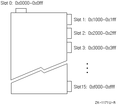
An EISA bus has 64K of I/O address space, and each slot is assigned a range of addresses, as follows:

Because each address range is reserved by its corresponding slot, the configuration file does not need to specifically allocate any resources for the board. If some initialization needs to occur at configuration time, you can accomplish this with the IOPORT statement.
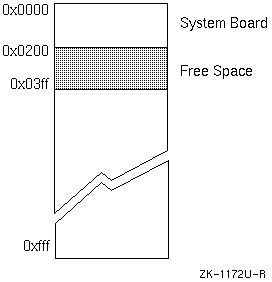
On ISA buses, the address range 0x0000 to 0x0fff is available for control status registers (CSRs) and low-speed data transfer (programmed I/O), as follows:

Within the address range 0x0200 and 0x03ff, each board must reserve the registers that it needs.
The Ethernet configuration file initializes two CSRs in I/O space. The first is at offset C0Ch from the beginning of the slot space. This space is used for the configuration register. The second is at offset C00h from the beginning of the slot space. This is used for network control and status.
IOPORT(1) = 0zC0Ch                ; Configuration Register
  SIZE = WORD
  INITVAL = 0000000xxxxxxxxxb


IOPORT(2) = 0zC00h                ; Network Control and Status
Register
  SIZE = WORD
  INITVAL = 0000000r00rrx000b
Note the use of the letter z in the I/O port address. It represents the slot number assigned to the board by the ECU.
CSRs are initialized with the values specified regardless of any other options that the user or the ECU chooses. When specifying the initial value, the letter r indicates that the bit value must be read from the port, x indicates that the ECU determines the bit value based on the selected configuration; b indicates that this is a binary value, or bit mask.
The ISA generic configuration file defines choices for 8, 16, and 32 port addresses. The user or the ECU can select the necessary ranges at configuration time. For example, the 32-bit addresses are defined as follows:
PORT= 200h-21Fh | 220h-23Fh | 240h-25Fh |
      260h-27Fh | 280h-29Fh | 2A0h-2BFh |
      2C0h-2DFh | 2E0h-2FFh |
      300h-31Fh | 320h-33Fh | 340h-35Fh |
      360h-37Fh | 380h-39Fh | 3A0h-3BFh |
      3C0h-3DFh | 3E0h-3FFh
The Microsoft sound board reserves two address ranges in I/O space. The first can be at any of three locations; the second must be at the specified location, as follows:
  CHOICE="Autosel resources"
    LINK
    PORT=0530h-0537h | 604h-60bh | 0E80h-0E87h
    LINK
    PORT=0388h-038bh
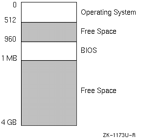
An EISA or ISA bus can support up to 32 bits of address space, or 4 GB of memory, for performing buffered I/O. Unlike I/O space, where the ranges of memory available to expansion boards are well defined, there are no reserved addresses within memory space. However, there are certain conventions that are widely recognized. A board that conforms to the following conventions is less likely to run into conflicts:

Digital UNIX does not use the space typically reserved for BIOS. Therefore, this space is also free for expansion boards.
Keep in mind that as operating systems become more sophisticated, they use more memory. Even in the 1 MB to 4 GB range, the expansion board may conflict with system memory. Therefore, you should try to reserve memory above the highest possible system address.
The Ethernet board uses memory space to read and write data across the network. The configuration file defines six possible memory configurations: three 64K buffers and three 32K buffers at varying addresses within memory space. The ECU picks the first block of memory that is available. For example:
FUNCTION = "Network Controller Buffer"
  CHOICE = "Address = 0D0000H - 0DFFFF (64K)"
    FREE
      MEMORY = 64K
        ADDRESS = 0D0000h
          MEMTYPE = OTHER
      INIT = IOPORT(1) LOC(2-0) 010
      INIT = IOPORT(2) LOC(3) 0


  CHOICE = "Address = 0E0000H - 0EFFFF (64K)"
    FREE
      MEMORY = 64K
        ADDRESS = 0E0000h
          MEMTYPE = OTHER
      INIT = IOPORT(1) LOC(2-0) 001
      INIT = IOPORT(2) LOC(3) 0


  CHOICE = "Address = 0C0000H - 0CFFFF (64K)"
    FREE
      MEMORY = 64K
        ADDRESS = 0C0000h
          MEMTYPE = OTHER
      INIT = IOPORT(1) LOC(2-0) 000
      INIT = IOPORT(2) LOC(3) 0


  CHOICE = "Address = 0D8000H - 0DFFFF (32K)"
    FREE
      MEMORY = 32K
        ADDRESS = 0D8000h
          MEMTYPE = OTHER
      INIT = IOPORT(1) LOC(2-0) 110
      INIT = IOPORT(2) LOC(3) 0


  CHOICE = "Address = 0C8000H - 0CFFFF (32K)"
    FREE
      MEMORY = 32K
        ADDRESS = 0C8000h
          MEMTYPE = OTHER
      INIT = IOPORT(1) LOC(2-0) 100
      INIT = IOPORT(2) LOC(3) 0


  CHOICE = "Address = 0E8000H - 0EFFFF (32K)"
    FREE
      MEMORY = 32K
        ADDRESS = 0E8000h
          MEMTYPE = OTHER
      INIT = IOPORT(1) LOC(2-0) 101
      INIT = IOPORT(2) LOC(3) 0
The ECU cannot sense the setting of jumpers or dip switches, and it cannot change those settings. To help users set jumpers and switches correctly, the ECU displays the proper settings. After running the ECU, the user sets the jumpers and switches as displayed, installs the board, and boots the system with the new configuration.
The Ethernet configuration file defines jumpers to show the user how to change from thinwire to thickwire connection, or vice versa. The following JUMPER statement defines the jumpers:
JUMPER(3) = 7
  NAME = "Network Select"
  JTYPE = TRIPOLE
  FACTORY = LOC(7-1) 0000000
  COMMENTS = "Thinwire/Twisted Pair Cable Selection, J1\n\n
\tTOP POSITION    = TWISTED PAIR\n
\tBOTTOM POSITION = THINWIRE"
The Network Interface function allows the user to select the type of connection. At that point, the internal representation of the jumpers is initialized, so the ECU can display the proper settings. For example:
FUNCTION = "Network Interface"
  COMMENTS = "
If the network interface selection is changed then the
network select jumper on J1 MUST be changed manually."
  CHOICE = "Thinwire"
  FREE
    INIT = JUMPER(3) LOC(7-1) 0000000
  CHOICE = "Twisted Pair"
  FREE
    INIT = JUMPER(3) LOC(7-1) 1111111
Running the ECU is slightly different for EISA and ISA buses. The procedure is outlined in Chapter 6, but you should consult your hardware manual for specific instructions.