This chapter provides an overview of the Digital UNIX Small Computer System Interface (SCSI) Common Access Method (CAM) Architecture (S/CA), which is a reliable, maintainable, and high-performance SCSI subsystem based on the industry-standard CAM architecture.
You should be familiar with the following documents:
Terms used in this guide, such as CAM control block (CCB), are defined in that document. You can purchase copies from Global Engineering, 2805 McGaw St, Irvine, CA 92714 (telephone: 800-854-7179).
You should also be familiar with the following two manuals, which are part of the Digital UNIX documentation:
This chapter describes the following:
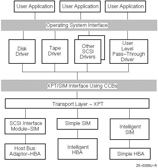
The CAM architecture defines a software model that is layered, providing hardware independence for SCSI device drivers and SCSI system software. In the CAM model, shown in Figure 1-1, a single SCSI/CAM peripheral driver controls SCSI devices of the same type, for example, direct access devices. This driver communicates with a device on the bus through a defined interface. Using this interface makes a SCSI/CAM peripheral device driver independent of the underlying SCSI Host Bus Adapter (HBA).
This hardware independence is achieved by using the Transport (XPT) and SCSI Interface Module (SIM) components of CAM. Because the XPT/SIM interface is defined and standardized, users and third parties can write SCSI/CAM peripheral device drivers for a variety of devices and use existing operating system support for SCSI. The drivers do not contain SCSI HBA dependencies; therefore, they can run on any hardware platform that has an XPT/SIM interface present.

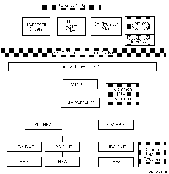
Figure 1-2 shows the Digital UNIX SCSI/CAM implementation of this model.

The User Agent driver routes user-process CAM control block (CCB) requests to the XPT for processing. The CCB contains all information required to fulfill the request. The user process calls the User Agent indirectly, using the ioctl(2) system call. A new User Agent CCB is allocated by a call to the XPT layer, and the user-process CCB information is copied into kernel space. The new CCB is filled in with the CCB values from the user process. If necessary, the user data areas are locked in memory. The CCB is then sent to the CAM subsystem for processing.
When the request has completed, the User Agent driver's completion routine is called. That routine performs all necessary cleanup operations and notifies the user process that the request is complete.
The User Agent allows multiple processes to issue CCBs, so there may be multiple processes sleeping on the User Agent. All CCBs are queued at the SIM layer.
SCSI/CAM peripheral device drivers convert operating system requests, such as user-process reads or writes, into CAM requests that the SCSI/CAM subsystem can process. Each type of SCSI/CAM peripheral driver is responsible for a specific class of SCSI device, such as SCSI tape devices. The SCSI/CAM peripheral driver handles error codes and conditions for its SCSI device class.
SCSI/CAM peripheral drivers convert input/output (I/O) requests into CAM control blocks (CCBs) that contain SCSI Command Descriptor Blocks (CDBs). CCBs are presented to the underlying transport layer, XPT, to initiate I/O requests. SCSI/CAM peripheral drivers implement SCSI device error recovery, for example, dynamic bad block replacement (DBBR). The SCSI device driver has no access to SCSI device control and status registers (CSRs) and receives no SCSI device interrupts.
The major/minor device-number pair, which is 32 bits wide, is used as an argument when creating the device special file associated with a specific SCSI device and is contained in the buf structure when accessing the device in raw or blocked mode. Figure 1-3 shows how the 32 bits are allocated.

This section provides overviews of the following:
Chapter 3, Chapter 4, and Chapter 11 describe the data structures and the routines associated with each module.
All the Digital UNIX SCSI/CAM peripheral drivers can share the common SCSI device driver structures and routines. Using these common routines can speed the process of writing a SCSI device driver because they are routines that any SCSI device driver can use to perform operations.
Digital supplies predefined data structures and formats that SCSI device driver writers can use to write generic SCSI/CAM peripheral device drivers. These data structures and formats can be used in conjunction with the common routines.
The SCSI/CAM peripheral disk driver supports removable (floppy) and nonremovable direct access SCSI disk devices and CD-ROM devices. The user interface consists of the major/minor device number pair and the ioctl commands supported by the SCSI disk device driver. The SCSI disk device driver also uses the common routines.
The SCSI tape device structures and routines are exclusive to the SCSI/CAM peripheral tape driver. The user interface consists of the major/minor device number pair and the ioctl commands supported by the SCSI tape device driver. The SCSI tape device driver also uses the common routines.
The SCSI CD-ROM/AUDIO device commands, which are described in Chapter 11, use the SCSI CD-ROM/AUDIO device structures. The SCSI CD-ROM/AUDIO device driver also uses the common routines.
The S/CA software includes an interface that processes special SCSI I/O control commands that the existing Digital SCSI subsystem uses to aid in porting new or existing SCSI device drivers from other vendors to the S/CA. With the SCSI/CAM special I/O interface, SCSI/CAM peripheral driver writers do not need detailed knowledge of either the system-specific or the CAM-specific structures and routines used to issue a SCSI command to the CAM I/O subsystem.
The configuration driver is responsible for configuring and initializing the CAM subsystem. This driver is also responsible for maintaining the cam_edt[] information structure.
When the system powers up, the configuration driver initializes the local and global CAM subsystem data structures. The configuration driver also calls the XPT and SIM initialization routines. When the subsystems are initialized, the configuration driver performs a SCSI-bus scan by sending the SCSI Device Inquiry command. The edt_dir[] structure contains pointers to the Equipment Device Table (EDT) structure for each bus. The EDT contains the returned SCSI inquiry data for the SCSI/CAM peripheral drivers to access. The drivers, using XPT_GDEV_TYPE and XPT_SDEV_TYPE, the get and set device information CCBs and can access the data contained in cam_edt[].
The CAM Transport layer (XPT) handles the CAM requests from the SCSI/CAM peripheral drivers and routes them to the appropriate SIM module. The XPT provides routines that are called by the SCSI/CAM peripheral driver to allocate and deallocate CAM control blocks (CCBs). In addition, the XPT provides routines that are used to initiate requests to the SIM and to issue asynchronous callbacks.
The SCSI Interface Module (SIM) has the most interaction with the SCSI bus protocol, timings, and other hardware-specific operations. Although this is a single component in the CAM model, it is divided into four logical sublayers in the Digital UNIX system: