| Previous | Contents | Index |
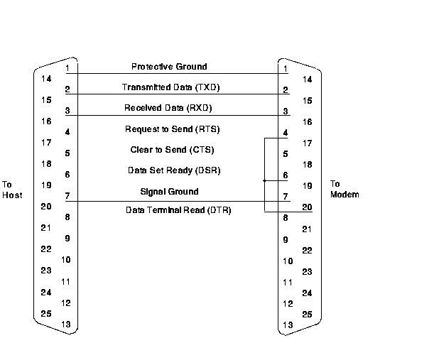
Figure A-1 shows the cable wiring and pin assignments from the processor to the J478 modem.
Figure A-1 Processor-to-Modem Connection
Modbus is an industrial communication network that can link one master to as many as 247 slaves. Specific masters may have restrictions that limit the number of slaves.
The host port modem is wired as the master on the Modbus. The master modem is connected by twisted-pair wire to all of the slave modems, such as a J478, that interface to the individual programmable controllers.
Figure A-2 represents a Modbus configuration.
Figure A-2 Modbus Block Diagram

Figure A-3 represents a Modbus-Plus configuration.
Figure A-3 Modbus Plus Block Diagram
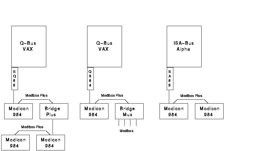
Figure A-4 represents a Modbus TCP/IP configuration.
Figure A-4 Modbus TCP/IP Block Diagram

| Previous | Next | Contents | Index |